Optical fiber F-P (Fabry-Perot) cavity pressure sensor with temperature self compensation

A pressure sensor, F-P technology, which is applied in the direction of force measurement by measuring the change of optical properties of the material when it is stressed, can solve the problems of reducing the pressure measurement accuracy of the optical fiber F-P cavity pressure sensor, etc.

Inactive Publication Date: 2014-03-19
BEIJING CHANGCHENG INST OF METROLOGY & MEASUREMENT AVIATION IND CORP OF CHINA
View PDF7 Cites 37 Cited by
  • Summary
  • Abstract
  • Description
  • Claims
  • Application Information

AI Technical Summary

Problems solved by technology

The sensitive element of the optical fiber F-P cavity pressure sensor - the F-P cavity is made of different materials, and different materials have different thermal expansion coefficients. When the ambient temperature changes, the size of th

Method used


Image

  • Optical fiber F-P (Fabry-Perot) cavity pressure sensor with temperature self compensation
  • Optical fiber F-P (Fabry-Perot) cavity pressure sensor with temperature self compensation
  • Optical fiber F-P (Fabry-Perot) cavity pressure sensor with temperature self compensation

Examples


Embodiment 1

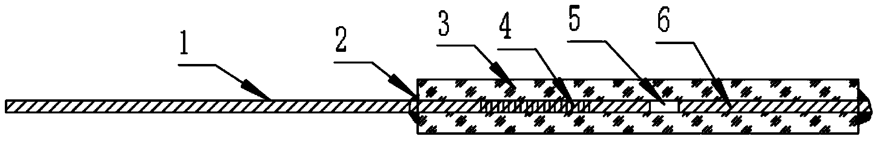
[0024] Such as figure 1 As shown, the fiber optic F-P cavity pressure sensor with temperature self-compensation, the sensing head of the sensor includes optical fiber A1, glass tube 3 and optical fiber B2;

[0025] A part of the optical fiber A1 is inserted into the glass tube 3, and the other part of the optical fiber A1 is located outside the glass tube 3, and is used as a conducting fiber to connect with peripheral demodulation equipment; welding;

[0026] The part of the optical fiber A1 inserted into the glass tube 3 is engraved with a grating 4;

[0027] The optical fiber B2 is completely inserted into the glass tube 3. In the glass tube 3, an F-P cavity is formed between the end faces of the optical fiber A1 and the optical fiber B2; the end face of the optical fiber A1 in the glass tube 3 is a reflective end face of the F-P cavity; The end face in the tube 3 is another reflective end face of the F-P cavity;

[0028] The above-mentioned sensor belongs to the lateral ...

Embodiment 2

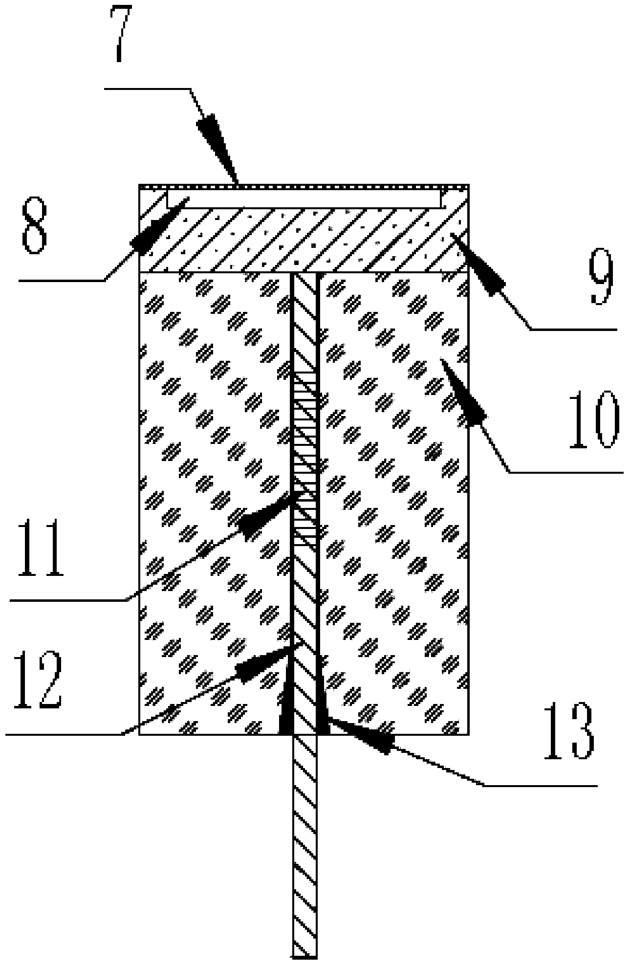
[0033] Such as figure 2 As shown, an optical fiber F-P cavity pressure sensor with temperature self-compensation, the sensing head of the sensor includes a diaphragm 7, a cavity bottom 9, a light guiding fiber 12 and a collimator 10;

[0034] There is a groove on the top of the cavity bottom 9, the diaphragm 7 and the cavity bottom 9 are bonded together by anodic bonding, and the F-P vacuum chamber 8 is formed between the diaphragm 7 and the groove;

[0035] The bottom end of the collimator tube 10 and the cavity bottom 9 is glued or welded by carbon dioxide laser;

[0036] The bottom end of the collimator 10 is drilled with a horn hole 13, the inner wall of the horn hole 13 is bonded with a layer of adhesive, a part of the light guiding fiber 12 is inserted into the collimating tube 10 through the horn hole 13, and the top of the light guiding fiber 12 It is flush with the lower surface of the cavity bottom 9; the part of the light guide fiber 12 inserted into the collimato...


PUM

PropertyMeasurementUnit
Outer diameteraaaaaaaaaa
The inside diameter ofaaaaaaaaaa
Lengthaaaaaaaaaa

Abstract

The invention belongs to the technical field of optical fiber sensing, and relates to an optical fiber F-P (Fabry-Perot) cavity pressure sensor with temperature self compensation. The F-P cavity pressure sensor with temperature self compensation adopts an optical fiber with an optical grating as a transmission optical fiber and adopts an optical F-P cavity as a pressure sensitive element, wherein the F-P cavity sensitive element is a non-intrinsic optical fiber F-P cavity, and the optical fiber gating and the optical F-P cavity are connected in a mode of glue bonding or carbon dioxide laser welding. According to the mode of pressure sensing, the sensor is divided into side pressure type optical fiber F-P cavity pressure sensors with temperature self compensation and end pressure type optical fiber F-P cavity pressure sensors with temperature self compensation.

Description

technical field [0001] The invention belongs to the technical field of optical fiber sensing and relates to an optical fiber F-P cavity pressure sensor with temperature self-compensation. Background technique [0002] The pressure sensor based on the optical fiber Fabry-Perot (F-P) cavity has the characteristics of resistance to harsh environments and anti-electromagnetic interference, and is suitable for pressure detection applications in the fields of medical treatment, aerospace, bridge construction, high-temperature oil wells, and national defense. The fiber optic sensor with Fabry-Perot Interferometer (FPI) structure has attracted widespread attention due to its simple structure, small size, high reliability, high sensitivity, short response time, and single-fiber signal transmission. , and has become one of the hot spots in the research of optical fiber sensing technology and its application in recent years. [0003] The sensitive end of the optical fiber F-P cavity p...

Claims


Application Information

Patent Timeline
IPC IPC(8): G01L1/24
Inventor 段玉培刘春红张慧君张立喆
Owner BEIJING CHANGCHENG INST OF METROLOGY & MEASUREMENT AVIATION IND CORP OF CHINA
Why Eureka
Try Eureka