Three-ring-shaped athermalized biosensor

A biosensor and three-ring technology, which is applied in the field of biosensors, can solve the problems of uneven temperature, area waste, and long distance between the reference microring and the detection microring, and achieves no need for temperature control devices, high integration, and avoidance of temperature uneven effect

Active Publication Date: 2014-03-19
UNITED MICROELECTRONICS CENT CO LTD
View PDF4 Cites 9 Cited by
  • Summary
  • Abstract
  • Description
  • Claims
  • Application Information

AI Technical Summary

Problems solved by technology

However, this method also has some inherent disadvantages
Due to the high integration characteristics of biosensors based on microring resonators, a chip can integrate hundreds of sensing units. If a whole biosensing chip is equipped with only one reference microring, there will be reference microrings and detection microrings. The distance is too far, and in the actual application process, if the temperature of the chip is not uniform, the reference microring cannot provide a valuable reference value
However, if a reference microring is arranged in each sensing unit, there will be a waste of area, which is not conducive to the design and manufacture of highly integrated biosensing chips.

Method used


Image

  • Three-ring-shaped athermalized biosensor
  • Three-ring-shaped athermalized biosensor
  • Three-ring-shaped athermalized biosensor

Examples


Embodiment Construction

[0033]In order to make the object, technical solution and advantages of the present invention clearer, the present invention will be further described in detail below in conjunction with the accompanying drawings and embodiments. It should be understood that the specific embodiments described here are only used to explain the present invention, not to limit the present invention.

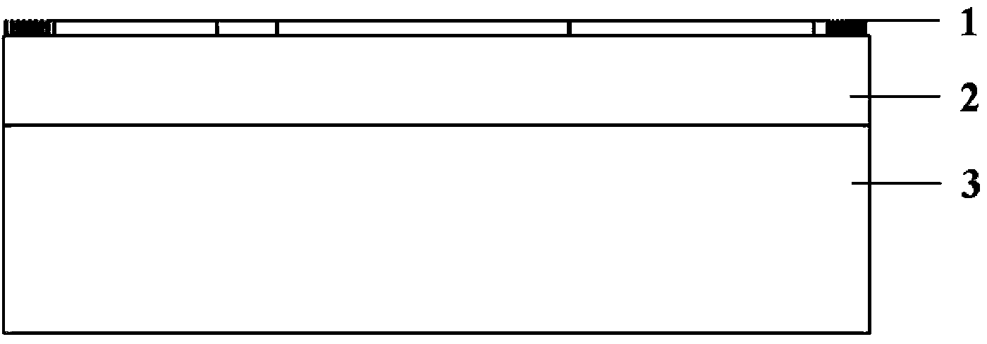
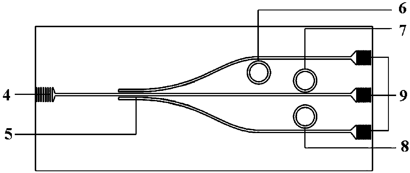
[0034] Such as figure 1 , 2 , 3, and 4 are schematic structural diagrams of the tricyclic athermal biosensor provided by the preferred embodiment of the present invention. The three-ring type athermal biosensor includes a substrate and a microstructure arranged on the substrate, and the microstructure includes: a main structure 1; an incident coupling grating 4; a three-way beam splitter 5; three microring resonators 6, 7 , 8; three outgoing coupling gratings 9.

[0035] The substrate includes a silicon dioxide buried layer 2 and a silicon substrate layer 3 , the tricyclic athermal biosensor main...


PUM

PropertyMeasurementUnit
Widthaaaaaaaaaa
Thicknessaaaaaaaaaa
Heightaaaaaaaaaa

Abstract

The invention discloses a three-ring-shaped athermalized biosensor. The three-ring-shaped athermalized biosensor comprises a base plate and a micro-structure arranged on the base plate, wherein the micro-structure comprises a main body structure, an incidence coupling optical grating, a three-path beam splitter, three micro-ring harmonic oscillators and three outgoing coupling optical gratings; one end of the main body structure is connected with the incidence coupling optical grating and the other end of the main body structure is connected with an input end of the three-path beam splitter; the three outgoing coupling optical gratings are arranged on three output ends of three branches of the three-path beam splitter respectively; the three micro-ring harmonic oscillators are arranged in parallel and are arrayed adjacently to the three branches of the three-path beam splitter; electromagnetic waves enter the main body structure from the incidence coupling optical grating, and then enter the three branches through the three-path beam splitter; then the electromagnetic waves are respectively coupled to enter the three micro-ring harmonic oscillators which are arrayed adjacently to the three branches, and are emitted out by the three outgoing coupling optical gratings; resonant wavelengths of the three micro-ring harmonic oscillators are different. The three-ring-shaped athermalized biosensor has the advantages of no need of a temperature control device, athermalization, high integration level, no limitation caused by preparation materials and the like.

Description

technical field [0001] The invention relates to a biosensor, in particular to a tricyclic athermal biosensor. Background technique [0002] Biosensors use biologically active units as biologically sensitive units and are highly selective detectors for analytes. They have important applications in environmental monitoring, biological defense, food testing, disease monitoring, and drug development. In recent years, with the development of photonic integration technology and the concept of Lab-on-a-chip (Lab-on-a-chip), biosensors based on optical waveguide microring resonators have fast detection speed, high sensitivity, and good real-time performance. , No labeling, no environmental and power frequency interference, etc., has become one of the research hotspots in the field of biosensing. [0003] The biosensor market is huge and is on the rise every year. According to Market Research, a professional company for market information feedback in the United States, the global bi...

Claims


Application Information

Patent Timeline
IPC IPC(8): G01N21/41
Inventor 崔乃迪郭进冯俊波滕婕王皖君
Owner UNITED MICROELECTRONICS CENT CO LTD
Why Eureka
Try Eureka