Long-wave infrared lens and infrared vehicle-mounted night vision system
A technology of long-wave infrared and lens, applied in the field of optical lens
- Summary
- Abstract
- Description
- Claims
- Application Information
AI Technical Summary
Problems solved by technology
Method used
Image

Examples
Embodiment 1
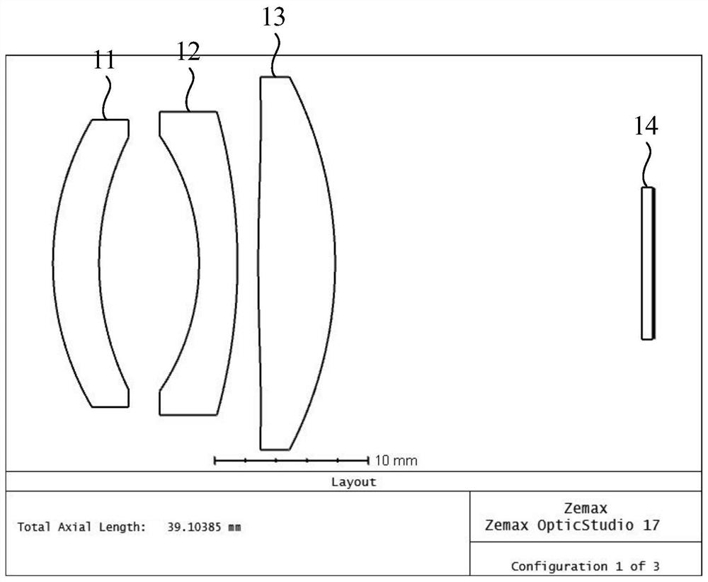
[0053] First, go ahead and refer to figure 1 The long-wave infrared lens in the first embodiment also includes a first lens 11, a second lens 12, and a third lens 13 arranged in sequence along the optical axis from the object side to the image side, and the first lens 11 has a convex surface facing the object side. A meniscus lens with positive refractive power; the second lens 12 is a lens with a negative refractive power with a concave surface facing the object side; the third lens 13 is a lens with a positive refractive power with a convex surface facing the object side; the long-wave infrared lens satisfies the following expression: 1.2< f*(n-1) / (FNO*R1)<2.39; wherein, f is the focal length of the long-wave infrared lens; FNO is the F number of the long-wave infrared lens; n is the central wavelength refractive index of the first lens 11; R1 is the first lens 11 The radius of curvature of the convex surface of a lens 11.
[0054] In the first embodiment, the field angle o...
Embodiment 2
[0069] Figure 11 It is a schematic structural diagram of another long-wave infrared lens provided in Embodiment 2 of the present invention, refer to Figure 11 , the field angle of the long-wave infrared lens of the second embodiment is 30°. Wherein, the object-side surfaces and image-side surfaces of the first lens 11 and the second lens 12 are both spherical surfaces. The object-side surface of the third lens 13 is a binary diffraction surface, and the image-side surface is an aspheric surface. Specifically, Table 4 is the optical data parameters of the long-wave infrared lens provided in the second embodiment, Table 5 is the binary diffraction surface and the aspherical data of the aspheric surface of the long-wave infrared lens provided in the second embodiment, and Table 6 is the data of the aspheric surface of the long-wave infrared lens provided in the second embodiment. Two provides the binary surface data of the binary diffraction surface of the LWIR lens.
[0070...
Embodiment 3
[0078] Figure 21 It is a schematic structural diagram of another long-wave infrared lens provided in Embodiment 3 of the present invention, refer to Figure 21 , the field angle of the long-wave infrared lens of the third embodiment is 40°. Wherein, the object-side surfaces and image-side surfaces of the first lens 11 and the second lens 12 are both spherical surfaces. The object-side surface of the third lens 13 is a binary diffraction surface, and the image-side surface is an aspheric surface. Specifically, in this embodiment, the focal length of the long-wave infrared lens is f=11mm, the aperture number FNO=1.2, and the maximum field of view 2ω=51.4°; the convex curvature radius R1 of the first lens 11=11.03mm, and the first lens 11 Focal length f1=41.079mm, the focal length f2=-11.955mm of the second lens 12, the focal length f3=7.464mm of the third lens 13; f*(n-1) / (FNO*R1)=2.01; f1 / f=3.73 ; f2 / f=-1.09; f3 / f=0.68.
[0079] Specifically, Table 7 is the optical data pa...
PUM
 Abstract
Description
Claims
Application Information
 - R&D
- Intellectual Property
- Life Sciences
- Materials
- Tech Scout
- Unparalleled Data Quality
- Higher Quality Content
- 60% Fewer Hallucinations
Browse by: Latest US Patents, China's latest patents, Technical Efficacy Thesaurus, Application Domain, Technology Topic, Popular Technical Reports.
© 2025 PatSnap. All rights reserved.Legal|Privacy policy|Modern Slavery Act Transparency Statement|Sitemap|About US| Contact US: help@patsnap.com