Whole flow field 3D visualization velocity measuring method

A technology of flow field and speed measurement, which is applied in the field of visual speed measurement of the whole flow field, and can solve problems such as complex structures

Inactive Publication Date: 2014-03-19
BEIJING INFORMATION SCI & TECH UNIV
View PDF4 Cites 15 Cited by
  • Summary
  • Abstract
  • Description
  • Claims
  • Application Information

AI Technical Summary

Problems solved by technology

However, the general structure is complex, and the full flow field information needs to be obtained through the movement of the focal plane of the objective lens, which is generally only suitable for steady flow

Method used


Image

  • Whole flow field 3D visualization velocity measuring method
  • Whole flow field 3D visualization velocity measuring method
  • Whole flow field 3D visualization velocity measuring method

Examples


Embodiment Construction

[0020] Embodiments of the present invention will be described in detail below in conjunction with the accompanying drawings.

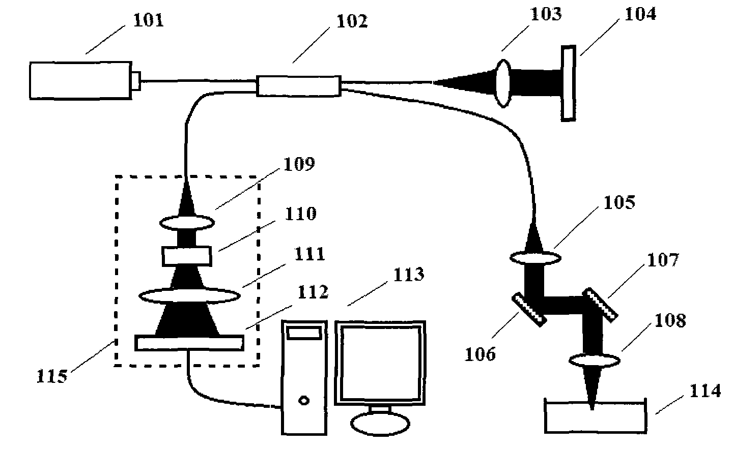
[0021] figure 1 It is a schematic diagram of a microparticle tracking full flow field visualization velocity measurement system based on frequency domain optical coherence tomography technology according to an embodiment of the present invention.

[0022] refer to figure 1 , the weakly coherent light emitted by the superluminescent light-emitting diode (SLD) (101) broadband light source enters the 2×2 fiber coupler (102) and is divided into two beams of light, one beam of light enters the reference arm and passes through the collimating lens (103) and the plane mirror (104), another beam of light enters the sample arm, and is incident on the measured fluid through the collimating lens (105), the two-dimensional galvanometer system (Y scanner 106 and X scanner 107), and the objective lens (108) (114). After the two beams of light return through the o...


PUM


Abstract

The invention discloses a whole flow field 3D visualization velocity measuring method for a microflow field, which comprises the steps of establishing a microparticle tracking whole flow field visualization velocity measuring system based on a frequency-domain optical coherence tomography technique; conducing two-dimensional scanning on a fluid, and continuously acquiring interference spectral data of the fluid; obtaining a three-dimensional image of the fluid based on a Fourier transform method; using local gray-level thresholding and volume filtering methods to search for the microparticles in the flow field, and using a squared weighted centroid method to obtain three-dimensional coordinates of the microparticles to achieve visualization of the microparticles; matching the microparticles by defining a cost function; and using variations in the three-dimensional coordinates of the microparticles to obtain a kinematic velocity vector. The visualization of velocity in the flow field is achieved through imaging and tracking of the microparticles; the three-dimensional velocity vector of the whole flow field is measured through tracking of moving trajectories of the microparticles in the whole flow field; and with micron-level spatial resolution, the whole flow field 3D visualization velocity measuring method is especially suitable for three-dimensional velocity vector detection of complex micro-fluid fields.

Description

technical field [0001] The invention relates to a full flow field visualization velocity measurement method. Especially the full flow field visualization velocity measurement method involving the micro flow field. Background technique [0002] Fluid velocity is the most basic physical quantity of flow field, and people's understanding of fluid flow characteristics largely depends on the acquisition of velocity field. So far, problems such as turbulence cannot be completely solved theoretically. We can only use scientific experiments to establish or improve fluid dynamics models and conduct more in-depth research on practical problems. Microfluidic devices are also more widely used in life sciences, chemistry, micromachining and other fields. The characteristics of microfluidics are more complex, and the role of scientific experiments is becoming more and more prominent. Methods for measuring flow velocity in fluids include mechanical methods, heat dissipation rate methods,...

Claims


Application Information

Patent Timeline
IPC IPC(8): G01P5/20
Inventor 刘国忠李萍
Owner BEIJING INFORMATION SCI & TECH UNIV
Why Eureka
Try Eureka