A fiber Bragg raster magnetic field sensor based on a current heat effect and an application method thereof

A magnetic field sensor and thermal effect technology, applied in the direction of the size/direction of the magnetic field, using electromagnetic devices to measure the magnetic field, etc.

Active Publication Date: 2014-03-19
KUNMING UNIV OF SCI & TECH
View PDF5 Cites 2 Cited by
  • Summary
  • Abstract
  • Description
  • Claims
  • Application Information

AI Technical Summary

Problems solved by technology

[0003] The detection technology close to the patent of the present invention is the fiber grating temperature and current sensor and its measuring device (see patent, patent publication number: CN 101033990A). The invention patent is composed of a fiber grating and a s...

Method used


Image

  • A fiber Bragg raster magnetic field sensor based on a current heat effect and an application method thereof

Examples


Embodiment 1

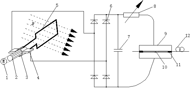
[0054] Embodiment 1: as figure 1 As shown, a fiber Bragg grating magnetic field sensor based on the current thermal effect includes a DC asynchronous motor 1, a motor shaft 2, a commutator 3, a brush 4, a rectangular coil 5, a bridge rectifier diode 6, a filter capacitor 7, and a variable Resistor 8, fiber Bragg grating 9, constantan sheet 10, polytetrafluoroethylene 11, externally connected optical fiber 12; DC asynchronous motor 1, motor shaft 2, commutator 3 and rectangular coil 5 are fixed together, brush 4 and The commutator 3 is in contact and the contact of the brush 4 is connected to the bridge rectifier diode 6 through wires, the lead-out end of the bridge rectifier diode 6 is connected to the filter capacitor 7 and the variable resistor 8, and the fiber Bragg grating 9 passes through the polytetrafluoroethylene Vinyl 11 is glued on constantan sheet 10 and connected with externally connected outgoing optical fiber 12 .

[0055] A rectangular square groove is cut out...

Embodiment 2

[0064] Embodiment 2: as figure 1 As shown, a fiber Bragg grating magnetic field sensor based on the current thermal effect includes a DC asynchronous motor 1, a motor shaft 2, a commutator 3, a brush 4, a rectangular coil 5, a bridge rectifier diode 6, a filter capacitor 7, and a variable Resistor 8, fiber Bragg grating 9, constantan sheet 10, polytetrafluoroethylene 11, externally connected optical fiber 12; DC asynchronous motor 1, motor shaft 2, commutator 3 and rectangular coil 5 are fixed together, brush 4 and The commutator 3 is in contact and the contact of the brush 4 is connected to the bridge rectifier diode 6 through wires, the lead-out end of the bridge rectifier diode 6 is connected to the filter capacitor 7 and the variable resistor 8, and the fiber Bragg grating 9 passes through the polytetrafluoroethylene Vinyl 11 is glued on constantan sheet 10 and connected with externally connected outgoing optical fiber 12 .

[0065] A rectangular square groove is cut out...


PUM

PropertyMeasurementUnit
Lengthaaaaaaaaaa
Densityaaaaaaaaaa
Thermal expansion coefficientaaaaaaaaaa

Abstract

The invention relates to a fiber Bragg raster magnetic field sensor based on a current heat effect and an application method thereof, and belongs to the technical field of photoelectron measurement. The fiber Bragg raster magnetic field sensor of the invention comprises a direct current asynchronous motor, an electric motor rotary shaft, a commutator, an electric brush, a rectangular coil, bridge type rectifier diodes, a filtering capacitor, a variable resistor, a fiber Bragg raster, a constantan piece, polytetrafluoroethylene, and an externally connected lead-out fiber. The direct current asynchronous motor, the electric motor rotary shaft and the commutator are fixed together with the rectangular coil. The electric brush contact with the commutator, and a contact of the electric brush is connected with the bridge type rectifier diodes through a conductive wire. A leading-out end of the bridge type rectifier diode is connected with the filtering capacitor and the variable resistor. The fiber Bragg raster is bonded to the constantan piece in an adhesive mode through the polytetrafluoroethylene, and is externally connected with the lead-out fiber. According to the invention, the size of a measurement scope of a magnetic field and the measurement sensitivity of the sensor can be adjusted; the resistance will not change as the temperature changes; the anti-interference capability is strong; the structure is simple; and the usage is convenient.

Description

technical field [0001] The invention relates to an optical fiber Bragg grating magnetic field sensor based on current thermal effect and a using method thereof, belonging to the technical field of optoelectronic measurement. Background technique [0002] Magnetic field measurement is involved in many fields of industrial production and scientific research, such as magnetic prospecting, geological exploration, magnetic material research, magnetic navigation, isodigit separation, controlled thermonuclear reaction, and artificial earth satellites. With the development of high-voltage direct current transmission and transformation, the monitoring of the magnetic field around substations and high-voltage transmission lines is of great significance to the safe operation of the power grid. For this reason, the optical fiber Bragg grating magnetic field sensor with electrical insulation, anti-electromagnetic interference, and all-optical communication has become an important researc...

Claims


Application Information

Patent Timeline
IPC IPC(8): G01R33/06
Inventor 李川赵成均陈富云王敏吉庄君刚赵振刚谢涛
Owner KUNMING UNIV OF SCI & TECH
Why Eureka
Try Eureka