Optical depolarizer

A depolarizer and optical technology, applied in the direction of coupling of optical waveguides, can solve the problems of unsuitable depolarizer, complicated operation process, inconvenient maintenance and installation, etc., and achieves a simple structure, guaranteed depolarization effect, and low optical loss. Effect

Active Publication Date: 2014-03-19
ZHUHAI GUANGKU TECH CO LTD
View PDF6 Cites 1 Cited by
  • Summary
  • Abstract
  • Description
  • Claims
  • Application Information

AI Technical Summary

Problems solved by technology

[0007] However, the above-mentioned depolarizer needs to use a polarization analyzer to detect the depolarization characteristics of the output light, and adjust the relative angle of the mold plate through the depolarization characteristics. The relative angle needs to be adjusted for different lights, and the operation process is relatively complicated. The user needs to precisely adjust the mold plate to get better depolarization light when using it, which makes the depolarizer not suitable for some complex and harsh environments, which brings inconvenience to the user when performing maintenance and installation outdoors and affects their work efficiency.

Method used


Image

  • Optical depolarizer
  • Optical depolarizer
  • Optical depolarizer

Examples


Embodiment Construction

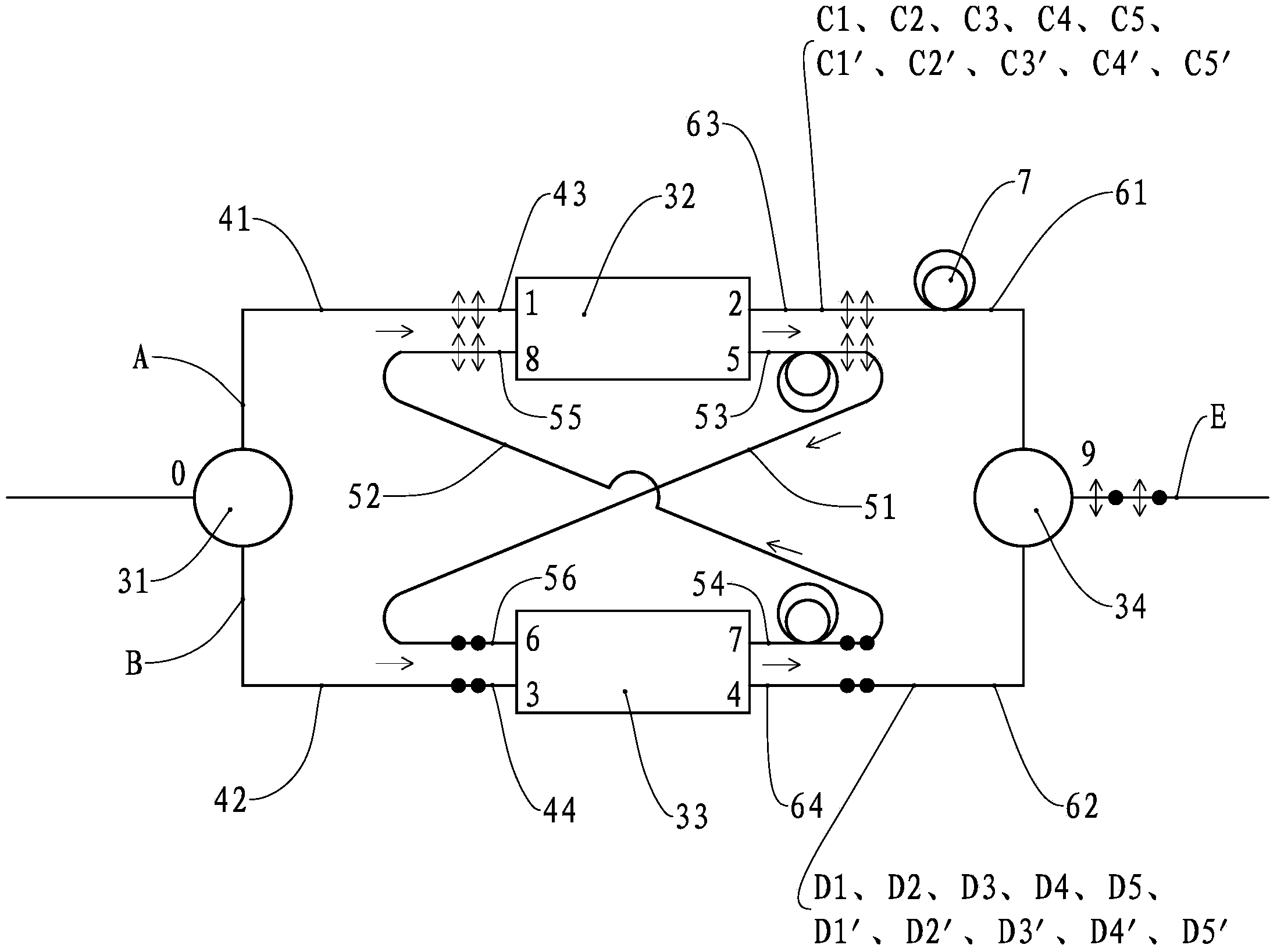
[0032] refer to image 3 , image 3 It is a structural diagram of the optical depolarizer of the present invention. The depolarizer includes a polarization beam splitter 31, a polarization maintaining coupler 32, a polarization maintaining coupler 33, and a polarization beam combiner 34, wherein the polarization maintaining coupler 32 is a 2×2 polarization maintaining coupler with a splitting ratio of 1:2 , the polarization maintaining coupler 32 includes an input port 1, an input port 8, an output port 2 and an output port 5, the polarization maintaining coupler 33 is a 2×2 polarization maintaining coupler with a splitting ratio of 1:2, and the polarization maintaining coupler 33 Including input port 3, input port 6, output port 4 and output port 7.

[0033] One output end of the polarization beam splitter 31 is connected to the input port 4 through an input polarization maintaining fiber 41 , and the other output end of the polarization beam splitter 31 is connected to the...


PUM


Abstract

The invention provides an optical depolarizer which comprises a polarization beam splitter, a first polarization-maintaining coupler, a second polarization-maintaining coupler, a first circulating polarization-maintaining optical fiber, a second polarization-maintaining optical fiber, a first output polarization-maintaining optical fiber, a second output polarization-maintaining optical fiber and a polarization beam combiner, wherein the first circulating polarization-maintaining optical fiber receives light emitted from the first polarization-maintaining coupler and light emitted to the second polarization-maintaining coupler; the second circulating polarization-maintaining optical fiber receives light emitted from the second polarization-maintaining coupler and light emitted to the first polarization-maintaining coupler; the length of the second circulating polarization-maintaining optical fiber is equal to the length of the first circulating polarization-maintaining optical fiber and more than the distance generated by the coherence time of light transmission; the first output polarization-maintaining optical fiber receives the light emitted from the first polarization-maintaining coupler; the second output polarization-maintaining optical fiber receives the light emitted from the second polarization-maintaining coupler; the length difference between the first output polarization-maintaining optical fiber and the second output polarization-maintaining optical fiber is more than the length of the first circulating polarization-maintaining optical fiber. The depolarizer with an all-optical fiber structure, which is provided by the invention, is simple in structure and convenient to use.

Description

technical field [0001] The invention relates to an optical device, in particular to an optical depolarizer for changing polarized light into non-polarized light. Background technique [0002] With the development of network communication, the data transmission speed of the optical fiber network is getting faster and faster, and the requirement for the capacity of the optical fiber network is also getting higher and higher. Most of the existing optical fiber networks transmit linearly polarized light, and the resulting polarization-dependent loss, polarization-dependent gain and other interferences sensitive to polarized light affect the quality of optical fiber network transmission signals. Therefore, some existing optical fiber networks use optical depolarizers to depolarize polarized light, so as to change polarized light into unpolarized light. [0003] The commonly used optical depolarizer is the Lyot depolarizer, which forms a time delay through the time difference bet...

Claims


Application Information

Patent Timeline
Patent Type & Authority Applications(China)
IPC IPC(8): G02B6/34
Inventor 傅谦王兴龙曹丁象刘侠张大龙
Owner ZHUHAI GUANGKU TECH CO LTD
Why Eureka
Try Eureka