
Skeleton type optical fiber ribbon cabling machine and cabling method using cabling machine

An optical fiber ribbon and cabling machine technology, applied in the direction of fiber mechanical structure, etc., can solve the problems of large accumulated error, fiber optic ribbon breakage, and cabling can not continue, and achieves the effect of ensuring the production process and smooth and smooth groove entry.

Active Publication Date: 2014-03-19
GUANGDONG HENGTONG PHOTOELECTRIC SCI & TECH +1
View PDF5 Cites 7 Cited by
  • Summary
  • Abstract
  • Description
  • Claims
  • Application Information

AI Technical Summary

Problems solved by technology

If there is a relative pitch error between the skeleton groove pitch and the stranded pitch, the pitch error will inevitably accumulate gradually. If the relative pitch error is unidirectional, the cumulative error will become larger and larger, and finally , the cabling will not be able to continue, and in severe cases, it will even cause the fiber ribbon entering the groove to break

Method used


Image

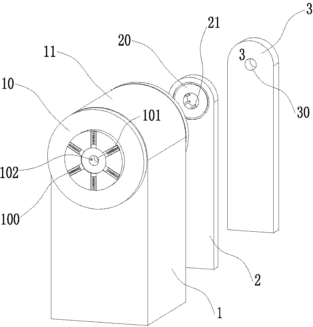
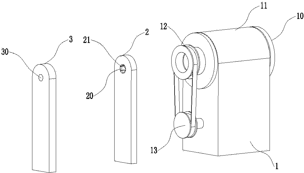
  • Skeleton type optical fiber ribbon cabling machine and cabling method using cabling machine
  • Skeleton type optical fiber ribbon cabling machine and cabling method using cabling machine

Examples


Embodiment Construction

[0025] The present invention is further described in conjunction with the following examples.

[0026] A skeleton type optical fiber ribbon cable forming machine, such as figure 1 As shown, it includes a console, a wire-feeding device, a trough-entry device and a wire-receiving device, wherein the wire-paying device, the trough-entry device and the wire-receiving device are all uniformly controlled by the console. The slotting equipment includes a twisting device 1 , a slotting die 2 and a sizing die 3 arranged in sequence along the advancing direction of the skeleton.

[0027] Such as figure 2 As shown, the twisting device 1 includes a twisting bearing seat 11 , a groove-in adjustment disc 10 , a sensing gear 12 and a sensing device 13 . Wherein, the sensing device 13 is provided with an angle sensor, and the slot-in adjustment disc 10 is connected with the sensing gear 12 through a hollow shaft, and the sensing gear 12 drives the sensing device 13 to rotate, and the sensi...


PUM


Abstract

The invention relates to the field of optical cable manufacturing, and particularly relates to a skeleton type optical fiber ribbon cabling machine and a cabling method using the skeleton type optical fiber ribbon cabling machine. The structure of the skeleton type optical fiber ribbon cabling machine comprises a control bench, a cable-releasing device, a groove-entering device and a cable-returning device. The groove-entering device comprises a twisting device which comprises a twisting bearing seat, a groove entering adjustment disc, a sensing gear and a sensing device. The sensing gear drives the sensing device to rotate. The groove entering adjustment disc is provided with a lead-in groove and a central hole. The central hole is internally provided with a protruding tooth which is embedded into a skeleton groove. The rotation state of the groove entering adjustment disc is detected via the sensing device and transmitted to the control bench. A rotation angle error is calculated via the control bench and distance between cabling twisted sections is automatically adjusted according to the rotation angle error so that the distance between the cabling twisted sections is matched with practical distance between the twisted sections of the skeleton groove, and an optical fiber ribbon is ensured to be stably and accurately put into the skeleton groove.

Description

technical field [0001] The invention relates to the field of optical cable manufacturing, in particular to a skeleton type optical fiber ribbon cable forming machine and a cable forming method using the cable forming machine. Background technique [0002] Skeleton optical fiber ribbon cable is more and more favored by construction units and users for its advantages of high fiber density, no grease filling, good lateral pressure resistance, excellent moisture resistance, and convenient connection. [0003] Skeleton optical cable is different from the way of filling buffer ointment around the optical fiber ribbon with loose sleeve structure. The skeleton structure does not go through the secondary coating process during manufacture, and the skeleton cable core is completed at one time in the process of bringing the optical fiber into the groove. The main manufacturing process of skeleton optical fiber ribbon cable is coloring, ribboning, cabling and sheathing. The process of ...

Claims


Application Information

Patent Timeline
Patent Type & Authority Applications(China)
IPC IPC(8): G02B6/44
Inventor 谭会良许征魏腾飞张小山刘婷陈龙张水仙夏巍习江华
Owner GUANGDONG HENGTONG PHOTOELECTRIC SCI & TECH
Learn More