A control method for traffic lamps and a system thereof

A control method and technology for traffic lights, applied in the field of transportation, can solve the problems of low travel efficiency, increased pollution, increased fuel consumption, etc., and achieve the effects of improving travel efficiency, alleviating road congestion, and avoiding vehicle waiting.

Inactive Publication Date: 2014-03-19
深圳市易车联网络科技有限公司
View PDF7 Cites 27 Cited by
  • Summary
  • Abstract
  • Description
  • Claims
  • Application Information

AI Technical Summary

Problems solved by technology

[0006] In order to solve the problems of road congestion, low travel efficiency and low vehicle speed caused by the e

Method used


Image

  • A control method for traffic lamps and a system thereof
  • A control method for traffic lamps and a system thereof

Examples


Embodiment 1

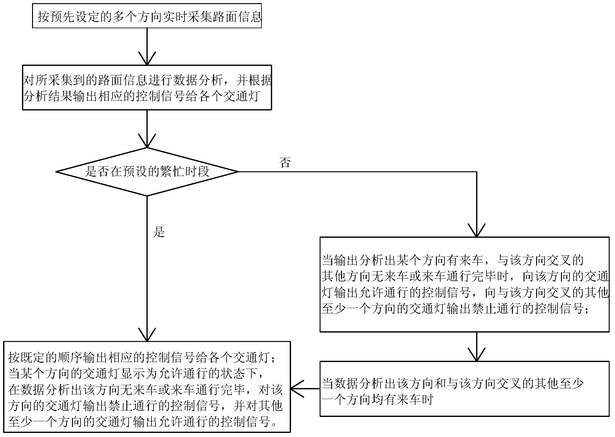
[0035] Such as figure 1 , a traffic light control method, comprising:

[0036] Real-time collection of road surface information in multiple preset directions;

[0037] Carry out data analysis on the collected road surface information, and output corresponding control signals to each traffic light according to the analysis results, that is, analyze the traffic conditions according to the collected road surface information, and determine the optimal working mode, and then press The optimal working mode outputs corresponding control signals to each traffic light to make traffic flow more smoothly, specifically including working modes 1 and 2, preferred working modes 3, 4 and 5, and error-correcting working modes. It should be noted that, According to the real-time road surface information, various working modes can be switched to each other:

[0038] Working mode one:

[0039] This working mode is suitable for busy periods, such as rush hours for commuting and commuting. The s...

Embodiment 2

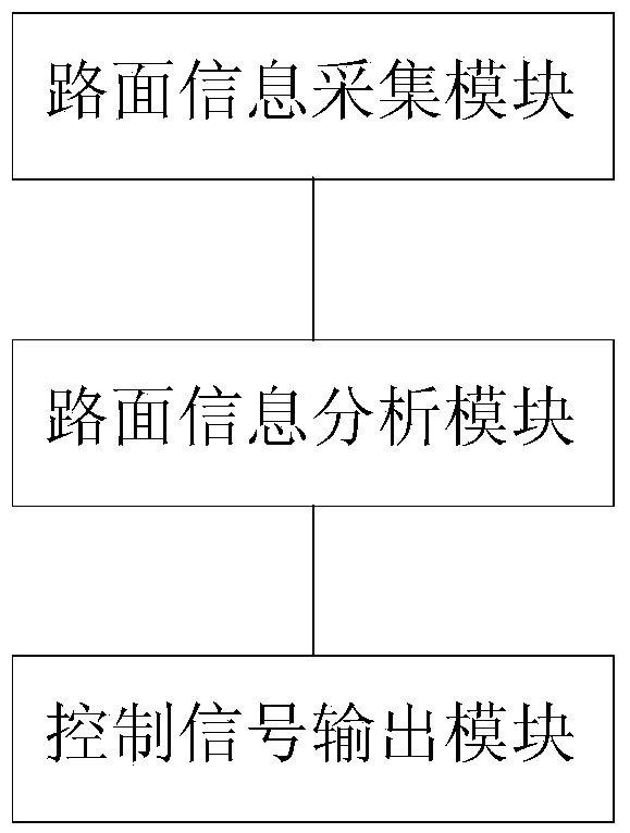
[0061] Such as figure 2 As shown, a traffic light control system includes:

[0062] The road surface information collection module is used to collect road surface information in real time in multiple preset directions; specifically, the road surface information collection module can use cameras, pressure sensors, etc., which are not limited here;

[0063] The road surface information analysis module is used to perform data analysis on the collected road surface information; the road surface information analysis module can adopt the existing image processing module or sensor data processing module;

[0064] The control signal output module is used to output corresponding control signals to each traffic light according to the analysis results, specifically including:

[0065] Working mode one:

[0066] During the predetermined busy period, output corresponding control signals to each traffic light in a predetermined order;

[0067] When the traffic light in a certain directi...


PUM


Abstract

The invention discloses a control method for traffic lamps and a system thereof. The method comprises the following steps: road information is acquired according to a plurality of preset directions in real time; data analysis is carried out on the acquired road information, and according to analysis results, control signals are output to various traffic lamps; specifically, a first work module in busy periods and a second work module in non-busy periods are included; in the busy periods of going to work and going off work, the control signals are output to the traffic lamps according to a preset sequence, and the traffic lamps can be temporarily adjusted to gives a direction in which vehicles come the priority of passage; and in the non-busy periods, the direction in which vehicles come is made to maintain in a green light state for a long time, and a direction in which none vehicle comes is made to maintain in a red light state for a long time until the road surface information changes, so that unnecessary waiting of the vehicles due to switching of the red light and the green light in a traditional mode is avoided. Conditions of road congestion are accordingly alleviated to a great extent. The travel efficiency and the vehicle driving speed are raised. Furthermore, the fuel oil consumption and the pollution are reduced.

Description

[technical field] [0001] The invention relates to the traffic field, in particular to a traffic light control method and system thereof. [Background technique] [0002] Since 2000, China has entered the era of automobiles. In 2012, the annual production and sales of automobiles exceeded 20 million, becoming a global automobile power. The ensuing problem is that urban traffic road congestion is serious year by year, especially in Beijing, Shanghai, Guangzhou, and Shenzhen. Road congestion brings the following problems: [0003] 1. Reduced travel efficiency. Originally, cars were used to improve work efficiency and save time, but now a lot of time is wasted on the road, which reduces the efficiency of the entire social and economic development; [0004] 2. Due to congestion, the driving speed of vehicles is greatly reduced, so that the running time of the car engine is increased for the same distance, and the fuel consumption is greatly increased. For example, the average spe...

Claims


Application Information

Patent Timeline
IPC IPC(8): G08G1/08
Inventor 李继朝梁斌
Owner 深圳市易车联网络科技有限公司
Why Eureka
Try Eureka