
Dynamic induction wireless charging system and charging system for vehicle

A wireless charging and charging system technology, which is applied in the field of vehicle charging system and dynamic induction wireless charging system, can solve the problems of battery replacement cost, environmental pollution, waiting for a certain time, etc.

Active Publication Date: 2017-09-19
ZONECHARGE (SHENZHEN) WIRELESS POWER TECH CO LTD
View PDF8 Cites 21 Cited by
  • Summary
  • Abstract
  • Description
  • Claims
  • Application Information

AI Technical Summary

Problems solved by technology

[0004] This will cause the car to stop for charging after driving for a period of time, and it needs to wait for a certain period of time when charging; if you want a long battery life, the vehicle needs to be equipped with a large on-board battery, and due to the aging of the battery, it is necessary to replace the battery. Cost issues and environmental pollution issues

Method used


Image

  • Dynamic induction wireless charging system and charging system for vehicle
  • Dynamic induction wireless charging system and charging system for vehicle
  • Dynamic induction wireless charging system and charging system for vehicle

Examples


Embodiment 1

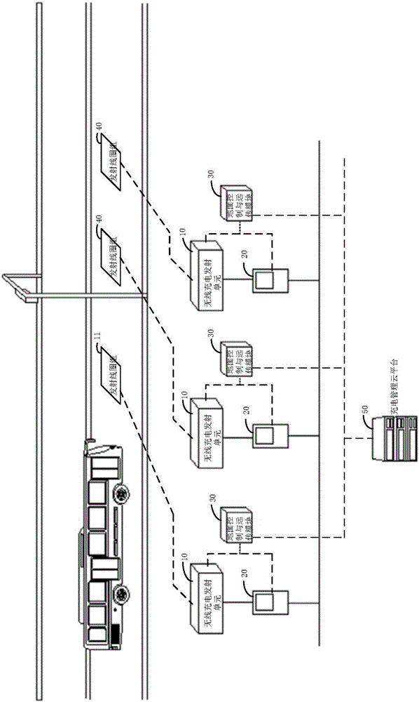
[0039] figure 1 It is a schematic diagram of a dynamic induction wireless charging system for vehicles provided by Embodiment 1 of the present invention.

[0040] refer to figure 1 , the system includes multiple wireless charging transmitting units 10, multiple electric energy metering systems 20, multiple ground control and remote transmission modules 30, and a charging management cloud platform 50, as well as a vehicle identification system and a monitoring system.

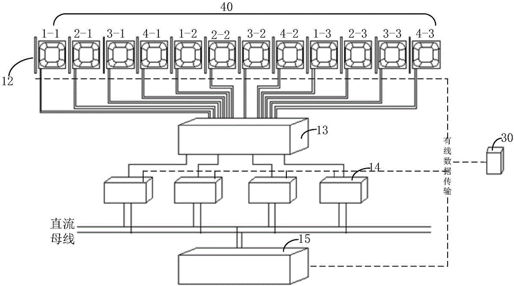
[0041] refer to figure 2 , the wireless charging transmitting unit 10 includes a coil switching control cabinet 13, a power supply cabinet, a position sensor 12 and a transmitting coil group 40, wherein the power supply cabinet includes 4 high-frequency inverter power supply cabinets 14 and 1 DC power supply cabinet 15, wherein the transmitting The coil set 40 includes 12 transmitting coils, and each transmitting coil is configured with a corresponding position sensor 12;

[0042]The coil switching control c...

Embodiment 2

[0064] Figure 5 It is a schematic structural diagram of a vehicle-mounted wireless charging system provided by Embodiment 2 of the present invention.

[0065] refer to Figure 5 , the charging system of the vehicle includes the mobile wireless charging system of the vehicle as described above, and also includes a wireless charging system 60 at the vehicle end, and the wireless charging system 60 at the vehicle end is arranged on the vehicle.

[0066] The vehicle-end wireless charging system 60 includes a vehicle-mounted control and remote transmission module, a vehicle-mounted battery, a pick-up coil, an impedance matching circuit, a synchronous rectification unit, and a DC-DC DC / DC converter. The DC side meter is connected with the output end of the DC / DC converter.

[0067] The number of pick-up coils can be multiple, specifically 1 to 3, and the power of each pick-up coil is 40KW. Different numbers of pick-up coils can be configured according to the received power, and 1...

Embodiment 3

[0069] Figure 6 It is a schematic diagram of the application of the charging management cloud platform provided by Embodiment 3 of the present invention.

[0070] refer to Figure 6 , the charging management cloud platform 50 obtains the total electricity on the AC side according to the electricity on the AC side generated by each wireless charging area, and sends the total electricity on the AC side to the ETC, and the ETC automatically settles when the vehicle leaves the exit of the wireless charging area. ETC is used for fee settlement based on the total electricity on the AC side.

[0071] The charging management cloud platform 50 can perform convenient payment and settlement, real-time charging service, charging energy efficiency management, data-based diagnosis and maintenance, data-based analysis and planning, fleet energy efficiency management, charging guidance and travel planning, etc.

[0072] The computer program product provided by the embodiments of the presen...


PUM


Abstract

The invention provides a dynamic induction wireless charging system and charging system for a vehicle. Either of the dynamic induction wireless charging system and the charging system for a vehicle comprises a position sensor for detecting the wheel position information of the vehicle, a coil switching control system for controlling the state of corresponding transmitting coils in a transmitting coil group according to the wheel position information, a power supply cabinet for supplying electric power according to the state of the corresponding transmitting coils in the transmitting coil group and charging the vehicle, and AC side electric quantity for calculating the AC side electric quantity generated by the vehicle passing through each wireless charging area and sending the AC side electric quantity generated by each wireless charging area to a charging management cloud platform through ground control and a remote transmission module, wherein the charging management cloud platform is used for obtaining the total AC side electric quantity according to the AC side electric quantity generated by each wireless charging area, so that the problem that a vehicle needs to wait during the charging process can be solved, endurance can be achieved without an on-board battery, the weight of the vehicle is reduced and secondary pollution caused by battery recycling is avoided.

Description

technical field [0001] The invention relates to the technical field of electric vehicles, in particular to a dynamic induction wireless charging system for vehicles and a charging system for vehicles. Background technique [0002] The dynamic wireless power supply technology uses the ground wireless power supply transmitter to wirelessly charge the moving electric vehicle to realize the battery life of the electric vehicle. [0003] The current wireless power supply for electric vehicles mainly adopts the method of supplementing power at fixed points. It is to set up fixed charging piles at certain fixed locations, and use the on-board battery between the two charging piles to solve the problem of battery life. [0004] This will cause the car to stop for charging after driving for a period of time, and it needs to wait for a certain period of time when charging; if you want a long battery life, the vehicle needs to be equipped with a large on-board battery, and due to the ...

Claims


Application Information

Patent Timeline
Patent Type & Authority Applications(China)
IPC IPC(8): B60L11/18H02J50/10G06Q50/06
CPCH02J50/10B60L53/12B60L53/36B60L53/665B60L53/39B60L53/38G06Q50/06B60L2210/10Y02T90/16B60L53/126Y02T10/70Y02T90/12Y02T10/7072Y02T90/14
Inventor 马邦华
Owner ZONECHARGE (SHENZHEN) WIRELESS POWER TECH CO LTD
Learn More