
Electronic circuit module and manufacturing method thereof

A technology of electronic circuit and production method, which is applied in the direction of printed circuit manufacturing, circuit, printed circuit, etc., and can solve problems such as difficult to obtain shielding effect, burr at cutting position, interface peeling, etc.

Inactive Publication Date: 2014-03-19
TAIYO YUDEN KK
View PDF5 Cites 7 Cited by
  • Summary
  • Abstract
  • Description
  • Claims
  • Application Information

AI Technical Summary

Problems solved by technology

That is, since the bonding force between metal and synthetic resin is smaller than the bonding force between the same metal or the bonding force between the same synthetic resin, when the shielding part is formed of conductive synthetic resin, the shielding part and the The bonding force between metal grounding wires decreases over time, and local peeling occurs at the interface, resulting in a decrease in the conductivity between the shield and the grounding wire, making it difficult to obtain the desired shielding. Effect
[0007] In addition, in the printed wiring board described in Patent Document 2, burrs may be generated at cutting positions corresponding to the four corners of the metal plate.
This burr comes into contact with the wiring layer or peripheral circuits formed on the insulating resin layer, causing problems such as short circuits.
However, in Patent Document 2, there is no specific description on how to suppress the generation of the burr.

Method used


Image

  • Electronic circuit module and manufacturing method thereof
  • Electronic circuit module and manufacturing method thereof
  • Electronic circuit module and manufacturing method thereof

Examples


Embodiment Construction

[0032] [Structure of electronic circuit module]

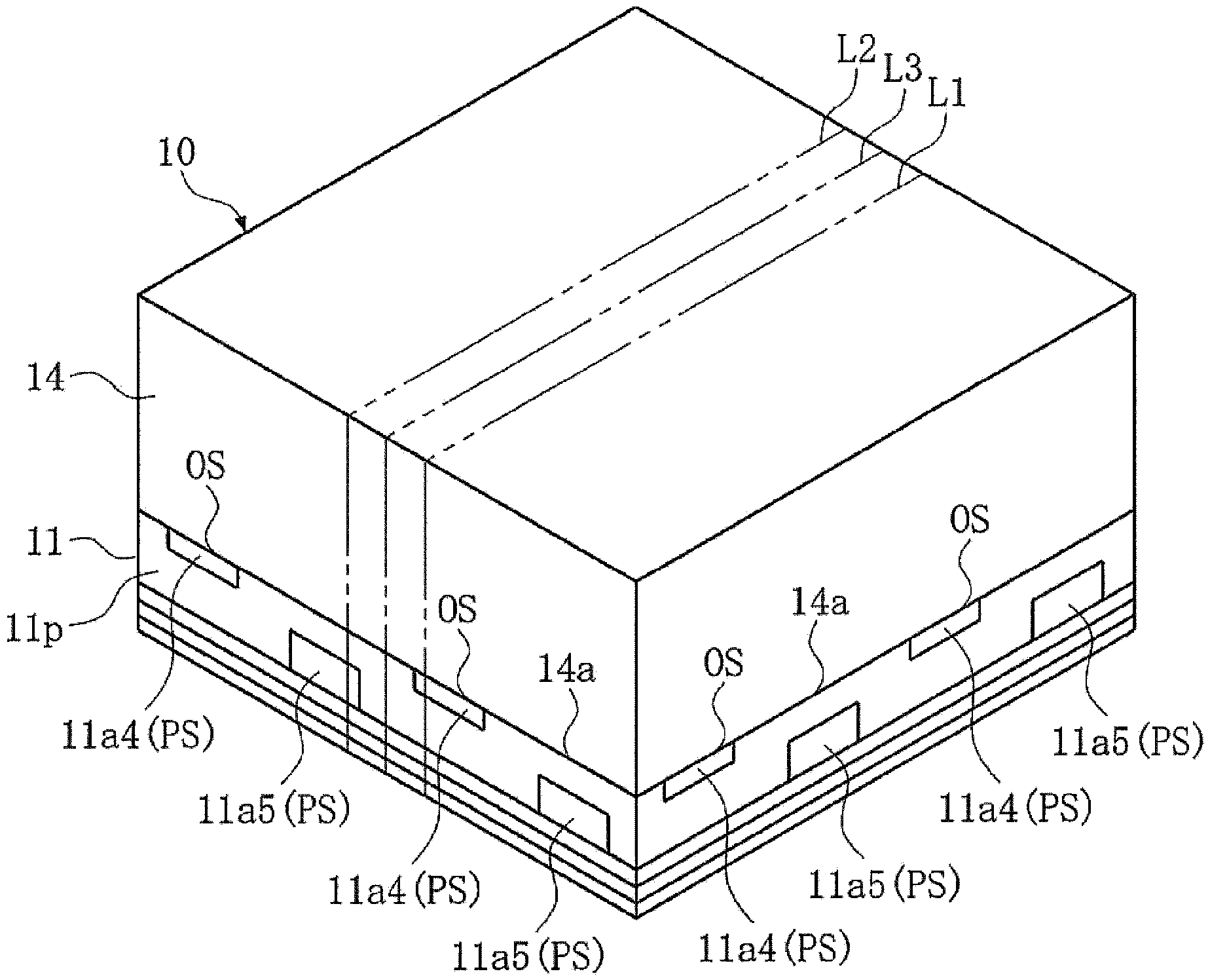
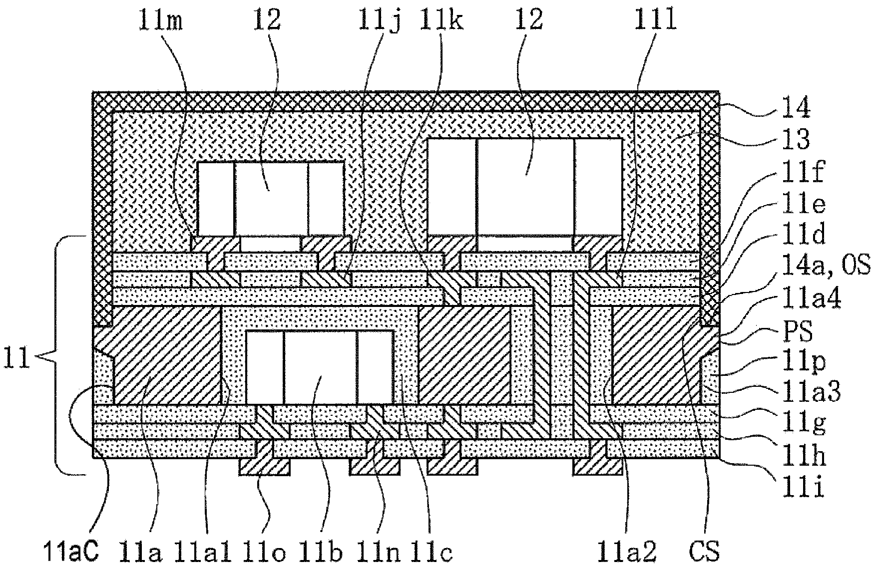
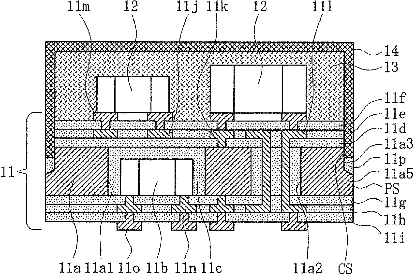
[0033] Figure 1 ~ Figure 5 The illustrated electronic circuit module 10 has: a component built-in substrate 11; a mounting component 12, which is mounted on the component built-in substrate 11; a package portion 13, which covers the mounting component 12; a shielding portion 14, which The electronic circuit is provided on the package part 13 and thus has a three-dimensional structure including the built-in component 11 b and the electronic circuit of the mounted component 12.

[0034] In addition, although Figure 2 ~ Figure 4 Position of the longitudinal section (refer to figure 1 Lines L1 to L3) are different, but for convenience of explanation, except Figure 2 ~ Figure 4 Except for the side surface portion of the base layer 11a described below, the other cross-sectional structures are the same.

[0035] Such as Figure 2 ~ Figure 4 As shown, the component built-in substrate 11 has: a base layer 11a; a built-in component 11b that...


PUM


Abstract

The invention provides an electronic circuit module and a manufacturing method thereof. The electronic circuit module comprises an element built-in substrate, surface-mounted elements, a packaging part and a shielding part. The element built-in substrate includes a metal base layer, an insulating outer installation part which is made of synthetic resin, and first projections. The base layer has corners and side surfaces, and is also used as a grounding line. The outer installation part covers the corners and the side surfaces, and has a first surface. The first projection has a first end face exposed by the external installation part, and a second surface adjacent to the first surface, and is projected outwardly at a position of the corner far away from the side surface. The surface-mounted elements are mounted on the element built-in substrate. The packaging part covers the surface-mounted elements. The shielding part is made of conductive synthetic resin, and covers the packaging part, and has a third surface attached to the first surface and the second surface.

Description

Technical field [0001] The present invention relates to an electronic circuit module and a manufacturing method thereof. The electronic circuit module has a packaging part covering a mounted component and a shielding part covering the packaging part. The mounted component is mounted in the built-in component On the substrate. Background technique [0002] Such electronic circuit modules are, for example, as described in Patent Document 1 below image 3 As shown, there are: a component built-in substrate; a mounting component, which is mounted on the component built-in substrate; a packaging part, which covers the mounting component; and a shielding part, which covers the packaging part. In this electronic circuit module, a predetermined electronic circuit including built-in components and mounted components is three-dimensionally mounted, and the intrusion of external noise is suppressed by the shielding portion connected to the ground wiring of the component built-in board. [000...

Claims


Application Information

Patent Timeline
IPC IPC(8): H05K3/00
CPCH01L24/97H05K7/06H01L2924/19105H05K9/00H05K13/0023H01L2224/97H01L2224/16225H01L21/561H01L23/552Y10T29/49146H01L2224/81
Inventor 猿渡达郎宫崎政志滨田芳树杉山裕一井田一昭
Owner TAIYO YUDEN KK
Learn More