
Frame structure for backrest and method for manufacturing same

A structure and frame technology, applied in applications, seat frames, household appliances, etc., can solve problems such as high cost, high cost, and difficult molding, and achieve high rigidity, high productivity, and lightness.

Active Publication Date: 2014-03-19
TORAY IND INC
View PDF8 Cites 6 Cited by
  • Summary
  • Abstract
  • Description
  • Claims
  • Application Information

AI Technical Summary

Problems solved by technology

However, in the structures disclosed in Patent Documents 2, 3, and 4, substantially the entire main constituent parts of the frame structure are made of FRP, that is, reinforcing fibers are arranged inside the thick walls of the main constituent parts. structure, therefore, it is often difficult to arrange the reinforcing fibers in the proper position and shape
As FRP, especially in the structure using CFRP (carbon fiber reinforced plastic) disclosed in Patent Documents 2 and 3, since the cost of CFRP is high, a high cost is required in this structure using a very large amount of CFRP
In addition, in order to provide a specific part of the frame structure described in Patent Document 2 with high rigidity, a concavo-convex structure or a plurality of ribs is provided, so this part has a relatively complicated shape, and it is relatively difficult to form in terms of making the whole into an integrated structure. difficult structure
As a result, there is room for improvement in terms of cheaper and easier manufacture of lightweight and highly rigid frame structures for backrests

Method used


Image

  • Frame structure for backrest and method for manufacturing same
  • Frame structure for backrest and method for manufacturing same
  • Frame structure for backrest and method for manufacturing same

Examples


Embodiment Construction

[0040] Hereinafter, preferred embodiments of the present invention will be described with reference to the drawings.

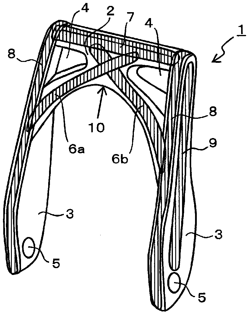
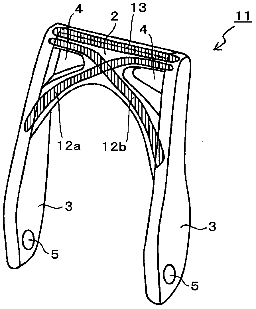
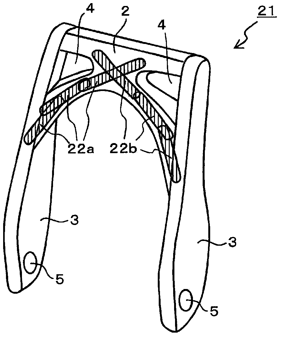
[0041] figure 1 A frame structure 1 for a backrest according to an embodiment of the present invention is shown. The frame structure 1 for the backrest is formed by integrally connecting side frames 3 extending parallel to each other on both sides and a horizontal frame 2 extending in the range between the upper parts of the frames 3 on both sides to form a gate shape as a whole. . A frame structure for a backrest made of a hard resin shows a frame structure for a backrest used in a vehicle seat. In this embodiment, openings 4 are provided on the left and right sides of the cross frame 2 mainly for weight reduction, and side frames 3 and support parts (support parts provided on vehicle seats) are formed on the lower parts of the side frames 3. , not shown in the figure), the connecting portion 5 (hole for connecting) supports the side frame 3 so that the sid...


PUM


Abstract

The present invention provides a resinous frame structure for a backrest and a method for manufacturing the same. The frame structure for the backrest has a configuration in which side frames that extend parallel to each other on both sides and a transverse frame that extends between the tops of both the side frames are integrally connected to form a gate shape as a whole, a belt-shaped FRP sheet in which reinforced fibers are oriented in one direction so as to stretch continuously or intermittently is stuck on the surface of at least the transverse frame between the side frames, and a matrix resin of the stuck FRP sheet and a resin constituting the transverse frame are integrally joined. The stiffness of the transverse frame that serves as a load receiving part and further forms a path for transmitting a load to the side frame side can be improved, and the whole frame structure can achieve high stiffness while ensuring light weight.

Description

technical field [0001] The present invention relates to a frame structure for a backrest and a manufacturing method thereof, and particularly relates to a frame structure for a backrest which is made of light resin but has high rigidity and is most suitable for use in an automobile seat, and a method for manufacturing the same. Background technique [0002] The frame structure for the backrest, especially the frame structure for the backrest of the vehicle, is desired to be lightweight in view of the requirement for reducing the overall weight of the vehicle, and it is required to withstand the load from the occupant when receiving a collision from the rear or side of the vehicle. To properly protect the occupant from the moment generated by such a large load, it is desirable that it is highly rigid. [0003] In the case where the frame structure is mainly made of metal, in order to satisfy the above-mentioned requirements, it becomes a relatively complicated structure (for ...

Claims


Application Information

Patent Timeline
Patent Type & Authority Applications(China)
IPC IPC(8): B60N2/68A47C7/40
CPCA47C7/40B29C45/14786B60N2/68
Inventor 松本贤山口晃司黑田义人
Owner TORAY IND INC
Learn More