Supercharge Your Innovation With Domain-Expert AI Agents!

Dedusting system combining flue gas ash conveying and filtering

A technology for conveying ash and flue gas, which is applied in the direction of dispersed particle filtration, dispersed particle separation, chemical instruments and methods, etc. It can solve the problems of high operating cost, severe wear and tear of conveying pipelines, and heavy maintenance workload, so as to reduce energy consumption and The effect of reducing operating costs, reducing maintenance workload, and saving steel consumption

Active Publication Date: 2014-03-26
WUXI XUELANG ENVIRONMENTAL TECH CO LTD
View PDF5 Cites 7 Cited by
  • Summary
  • Abstract
  • Description
  • Claims
  • Application Information

AI Technical Summary

Problems solved by technology

Scraper conveyors are severely worn when conveying ash, have a short service life, need to be replaced regularly, have a relatively large maintenance workload, and have high operating costs; the pneumatic conveying system requires compressed air, and the energy consumption is relatively high, and the conveying pipes are severely worn and easily blocked, which will affect system running

Method used


Image

  • Dedusting system combining flue gas ash conveying and filtering
  • Dedusting system combining flue gas ash conveying and filtering

Examples


specific Embodiment 1

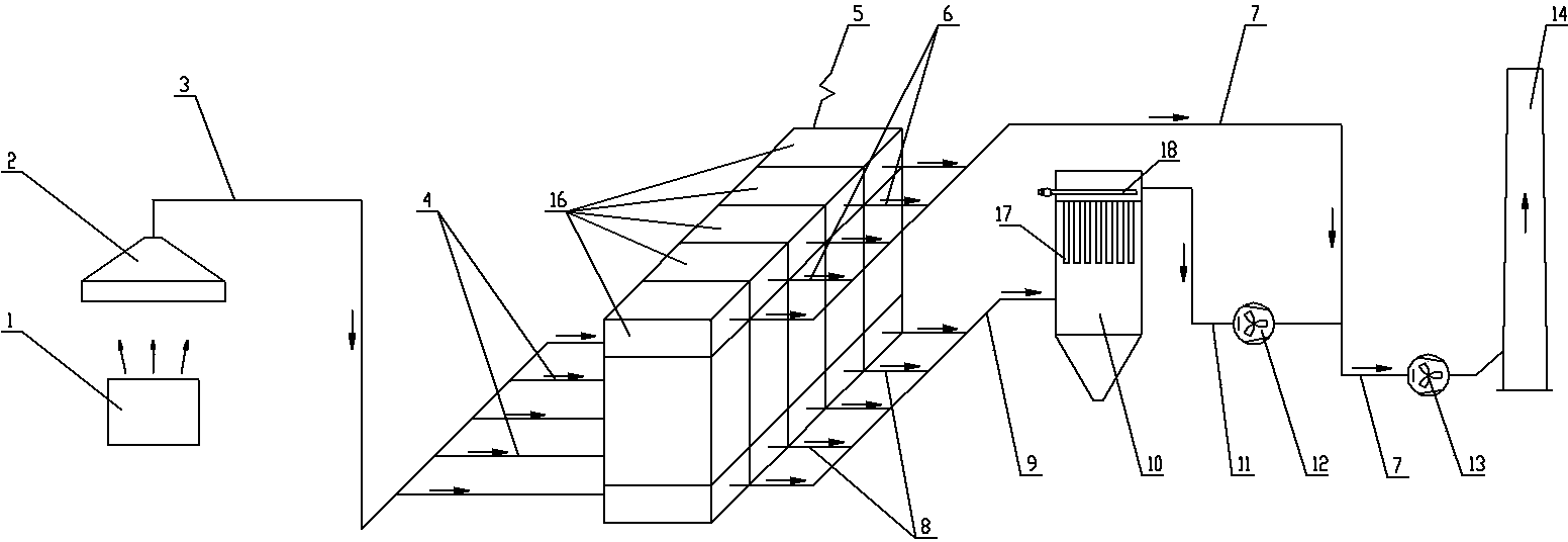
[0011] Specific embodiment one: see figure 1 , the end of the clean air main pipe 7 is directly connected to the bottom air inlet of the chimney 14, the clean air pipe 11 connects the middle part of the clean air main pipe 7, and the dust removal fan 13 is positioned at the rear of the end of the clean air pipe 11.

[0012] Its working principle is as follows: its workflow is as follows:

[0013] The flue gas or dust emitted by the dust source 1 is captured by the collection hood 2, and the collected flue gas or dust enters the flue gas main pipe 3, and then enters the corresponding chamber of the dust collector 5 through each flue gas branch pipe 4 for dust removal. The clean gas after dedusting in each chamber enters each clean gas branch pipe 6, then enters the clean gas main pipe 7, and finally is sent to the chimney 9 by the dust removal fan 8 through the clean gas main pipe 7 for discharge.

[0014] Dust removal in dust collector 5 is carried out room by room in sequenc...

specific Embodiment 2

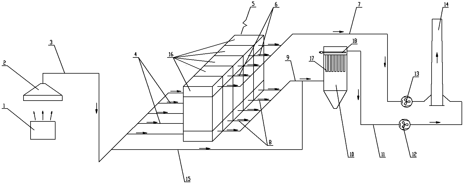
[0015] Specific embodiment two: see figure 2 , the clean gas main pipe 7 and the clean air pipe 11 are respectively connected to the bottom air inlet of the chimney 14, and the flue gas main pipe 3 is connected to the ash conveying main pipe 9 through the bypass pipe 15.

[0016] Its working principle is as follows: the flue gas or dust emitted by the dust source 1 is captured by the collecting cover 2, and the collected flue gas or dust enters the flue gas main pipe 3, and then most of the flue gas or dust passes through each flue gas branch pipe 4 Enter the chambers corresponding to the dust collector 5 for dust removal, and the clean gas after dedusting in each chamber enters each clean gas branch pipe 6, and then enters the clean gas main pipe 7, and finally is sent to the chimney 9 by the dust removal fan 8 through the clean gas main pipe 7. Emission; another part of flue gas or dust successively enters the ash storage bin 10 through the bypass pipe 15 and the ash convey...


PUM


Abstract

The invention provides a dedusting system combining flue gas ash conveying and filtering, flue gas is used as a carrier for conveying dust removed by a deduster into an ash bin, the repair workload can be reduced, the energy consumption and operation cost can be reduced, the size of a deduster can be minified, the steel use amount can be saved, and the investment cost can be reduced. The dedusting system comprises a dust source, a collecting cover, the deduster, the ash bin, a dedusting fan and a chimney, an upper outlet of the chimney is communicated with the atmosphere, the collecting cover is arranged above the dust source, the dedusting system is characterized in that: the deduster comprises at least two chambers, the flue gas collected by the collecting cover is distributed to each flue gas branch pipe through a flue gas header pipe, the flue gas branch pipe is respectively leaded into one inlet on one side of the bottom of a corresponding chamber of the deduster, the top of each chamber of the deduster is connected into a net gas header pipe by a corresponding net gas branch pipe, and one outlet on the other side of the bottom of the chamber of the deduster is connected into an ash conveying header pipe by a corresponding ash conveying branch pipe.

Description

technical field [0001] The invention relates to the technical field of energy saving and environmental protection, in particular to a dust removal system combining flue gas ash conveying and filtering. Background technique [0002] The existing dust removal system is mainly composed of dust sources, collection hoods, dust collectors, dust removal fans, dust removal pipes, chimneys, etc., and is equipped with scraper conveyors or pneumatic conveying systems, ash storage bins, dust collector ash hoppers, etc. When using a scraper conveyor or a pneumatic conveying system to transport the dust to the ash storage bin. Scraper conveyors are severely worn when conveying ash, have a short service life, need to be replaced regularly, have a relatively large maintenance workload, and have high operating costs; the pneumatic conveying system requires compressed air, and the energy consumption is relatively high, and the conveying pipes are severely worn and easily blocked, which will a...

Claims


Application Information

Patent Timeline
Patent Type & Authority Applications(China)
IPC IPC(8): B01D46/00B01D46/04B01D46/42
Inventor 尹华勤
Owner WUXI XUELANG ENVIRONMENTAL TECH CO LTD
Features
  • R&D
  • Intellectual Property
  • Life Sciences
  • Materials
  • Tech Scout
  • Unparalleled Data Quality
  • Higher Quality Content
  • 60% Fewer Hallucinations
Learn More