Threaded hole cleaner

A technology for cleaning devices and threaded holes, applied in cleaning methods and tools, cleaning methods using liquids, chemical instruments and methods, etc., can solve problems such as mutual blow-by, affect engine performance, ablate cylinder pads, etc., and achieve high efficiency cleaning effect

Inactive Publication Date: 2014-03-26
ZHENJIANG DAXING MACHINERY MFG
View PDF6 Cites 4 Cited by
  • Summary
  • Abstract
  • Description
  • Claims
  • Application Information

AI Technical Summary

Problems solved by technology

When the engine runs for a period of time, it will cause the blow-by between the cylinders, which

Method used


Image

  • Threaded hole cleaner
  • Threaded hole cleaner

Examples


Example Embodiment

[0009] The present invention will be further explained below in conjunction with the drawings.

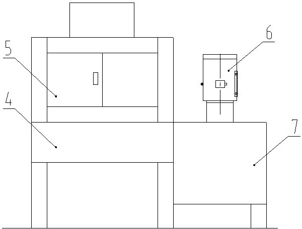
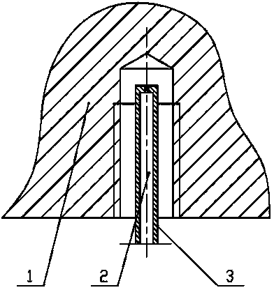
[0010] Such as figure 1 , 2 As shown, the threaded hole cleaning device of the present invention includes a nozzle 3, a sedimentation tank 4, a cleaning tank 5, a high-pressure water pump 6 and a water tank 7.

[0011] The nozzle is connected to the outlet of the high-pressure water pump. The number of nozzles depends on the number of threaded holes on the workpiece to be cleaned. Put the workpiece 1 to be cleaned into the cleaning box, insert the nozzle into the threaded hole of the workpiece to be cleaned 1, and start the high-pressure water pump. The high-pressure cleaning water 2 produced by the high-pressure water pump is injected into the bottom of the threaded hole through the nozzle, so that the iron filings adsorbed in the threaded groove and deposited on the bottom of the threaded hole are carried out with the water flow.

[0012] Preferably, the threaded hole cleaning device in...


PUM


Abstract

The invention relates to a threaded hole cleaner, and belongs to the technical field of metal processing equipment. The threaded hole cleaner comprises a high-pressure water pump and a nozzle connected to the high-pressure water pump, and the external diameter of the nozzle is smaller than the internal diameter of a to-be-cleaned threaded hole. When the threaded hole cleaner is operated, a to-be-cleaned workpiece is put in a cleaning tank, the nozzle is inserted into a threaded hole, the high-pressure water pump is started, high-pressure cleaning water generated by the high-pressure water pump is enabled to be injected into the threaded hole via the nozzle, and sundries such as scrap iron absorbed in a thread groove and deposited at the bottom of the threaded hole are brought out with water flow by the aid of impact force generated by the high-pressure cleaning water, and accordingly the advantage of rapidly and efficiently cleaning the threaded hole is realized. As a further improvement, the threaded hole cleaner comprises a temperature control device, the high-pressure cleaning water is controlled at the temperature of 60 DEG C through the temperature control device, and residual oil fouling in the processing process of the to-be-treated workpiece is cleaned more thoroughly.

Description

technical field [0001] The invention belongs to the technical field of metal processing, and in particular relates to a cleaning device for blind hole threads. Background technique [0002] There are many and deep holes on the cylinder block and cylinder head of the engine, and most of them are blind holes. The processed iron filings are deposited at the bottom of the holes. In most cases, the mixture of iron filings and sludge is adsorbed in the thread groove. It is very difficult to clean these parts, and the residual iron filings in the holes have seriously affected the cleanliness of the engine, and are particularly harmful to the whole machine. For example, the residual iron filings in the threaded hole of the main bearing of the cylinder block will easily form the phenomenon of false torque of the main bearing bolts, causing the main bearing cover to loosen, resulting in crankshaft fracture or burning, and engine vibration. Another example is that when there are resid...

Claims


Application Information

Patent Timeline
IPC IPC(8): B08B3/02B08B3/10
CPCB08B3/02B08B3/10
Inventor 季建平
Owner ZHENJIANG DAXING MACHINERY MFG
Why Eureka
Try Eureka