A device and application for preparing metal semi-solid slurry

A semi-solid slurry and metal technology, applied in the field of material science, can solve the problems of high energy consumption, long preparation time, and poor effect of grain refinement, and achieve easy parameter control, simple operation, and grain refinement. Effect

Active Publication Date: 2017-01-04
KUNMING UNIV OF SCI & TECH
View PDF5 Cites 0 Cited by
  • Summary
  • Abstract
  • Description
  • Claims
  • Application Information

AI Technical Summary

Problems solved by technology

[0005] The traditional electromagnetic stirring technology is to vigorously stir the primary phase of the alloy growing in the form of dendrites during the solidification process, so that the dendrites break and enter the melt to realize the doubling of the grains. The stronger the stirring, the greater the grain size. The more obvious the doubling phenomenon, the finer the grains, but this traditional electromagnetic stirring technology pulping method consumes a lot of energy, takes a long time to prepare, and when the stirring intensity exceeds a certain value, due to the collision between the grains, the grains become finer. The effect of chemicalization becomes worse

Method used


Image

  • A device and application for preparing metal semi-solid slurry
  • A device and application for preparing metal semi-solid slurry
  • A device and application for preparing metal semi-solid slurry

Examples


Embodiment 1

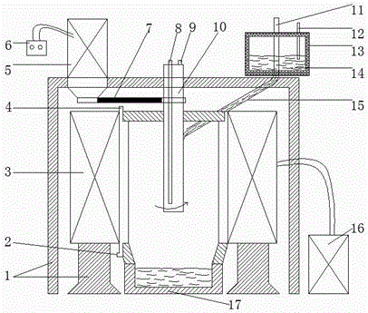
[0027] The device for preparing metal semi-solid slurry described in this embodiment includes: a support frame 1, a magnetic field generator 3, a speed regulating motor 5, a speed controller 6, a transmission belt 7, a rotating rod 10, a graphite stopper rod 11, a thermocouple 12, The furnace 13, the runner 15, the current controller 16, the crystallizer 17, the magnetic field generator 3, the speed regulating motor 5, and the furnace 13 are fixed on the support frame 1, and the rotating rod 10 is fixed on the support frame 1 and located on the magnetic field generator 3 In the inner cavity of the inner cavity, the speed regulating motor 5 is connected with the rotating rod 10 through the transmission belt 7, and the furnace 13 is provided with a graphite stopper rod 11, a thermocouple 12, and a runner 15, and the runner 15 communicates with the furnace 13, and the runner 15 The inlet is located at the lower end of the graphite stopper rod 11, the outlet of the runner 15 faces ...

Embodiment 2

[0035] The device for preparing metal semi-solid slurry described in this embodiment includes: a support frame 1, a magnetic field generator 3, a speed regulating motor 5, a speed controller 6, a transmission belt 7, a rotating rod 10, a graphite stopper rod 11, a thermocouple 12, The furnace 13, the runner 15, the current controller 16, the crystallizer 17, the magnetic field generator 3, the speed regulating motor 5, and the furnace 13 are fixed on the support frame 1, and the rotating rod 10 is fixed on the support frame 1 and located on the magnetic field generator 3 In the inner cavity of the inner cavity, the speed regulating motor 5 is connected with the rotating rod 10 through the transmission belt 7, and the furnace 13 is provided with a graphite stopper rod 11, a thermocouple 12, and a runner 15, and the runner 15 communicates with the furnace 13, and the runner 15 The inlet is located at the lower end of the graphite stopper rod 11, the outlet of the runner 15 faces ...

Embodiment 3

[0043] The device for preparing metal semi-solid slurry described in this embodiment includes: a support frame 1, a magnetic field generator 3, a speed regulating motor 5, a speed controller 6, a transmission belt 7, a rotating rod 10, a graphite stopper rod 11, a thermocouple 12, The furnace 13, the runner 15, the current controller 16, the crystallizer 17, the magnetic field generator 3, the speed regulating motor 5, and the furnace 13 are fixed on the support frame 1, and the rotating rod 10 is fixed on the support frame 1 and located on the magnetic field generator 3 In the inner cavity of the inner cavity, the speed regulating motor 5 is connected with the rotating rod 10 through the transmission belt 7, and the furnace 13 is provided with a graphite stopper rod 11, a thermocouple 12, and a runner 15, and the runner 15 communicates with the furnace 13, and the runner 15 The inlet is located at the lower end of the graphite stopper rod 11, the outlet of the runner 15 faces ...


PUM


Abstract

The invention discloses a device and application for preparing metal semi-solid slurry, and belongs to the technical field of material science. The device is composed of a smelting furnace, a rotating stick induction nucleation system, a rotating magnetic field generator and a crystallizer. After being preheated to the preset temperature, overheated metal melt passes through a pouring gate to be right opposite to a rotating stick to pour the rotating stick, under the action of the tangential force of the rotating stick, molten metal is spread out by surrounding the rotating stick to form a melt thin film, the whole melt is undercooled, and a large amount of nucleation of a primary phase inside the melt thin film is induced; due to the existence of a magnetic field, a liquid film is evenly spread around the rotating stick, and even undercooling is generated; after being temporarily spread out, the melt thin film flies away from the rotating stick, the primary phase is prevented from further growing, and finally small and spherical or similarly spherical microstructures are obtained. According to the device, the round semi-solid alloy slurry of the even structures is obtained by controlling the temperature and the flow rate of the metal melt, the rotating speed of the rotating stick and the current of the magnetic field generator.

Description

technical field [0001] The invention relates to a device and application for preparing metal semi-solid slurry, belonging to the technical field of material science. Background technique [0002] Semi-Solid Forming of Metals (Semi-Solid Forming of Metals) is to change the nucleation and growth of the primary solid phase by vigorously stirring it and adding grain refiners during the solidification process of metals with a certain solid-liquid interval. Through a large process, a solid-liquid mixed slurry with fine, round and evenly distributed grains is obtained. [0003] Since the metal semi-solid forming technology was discovered and proposed by the research team of Flemings of the Massachusetts Institute of Technology in the 1970s, domestic and foreign scholars have proposed many methods for preparing semi-solid slurry, among which electromagnetic stirring technology occupies a dominant position. Electromagnetic stirring is different from mechanical stirring. It will not ...

Claims


Application Information

Patent Timeline
Patent Type & Authority Patents(China)
IPC IPC(8): B22D27/00B22D27/02
Inventor 周荣锋何志坚陈宗宝蒋业华周荣卢德宏
Owner KUNMING UNIV OF SCI & TECH
Why Eureka
Try Eureka