
Rotary knife, manufacturing method thereof, and rotary cutting device

A manufacturing method and technology of rotating knife, applied in thin material processing, metal processing, sending objects, etc., can solve problems such as sheet separation, low installation accuracy, damage to cutting tool characteristics, etc.

Active Publication Date: 2016-09-28
HITACHI METALS PRECISION LTD +1
View PDF11 Cites 0 Cited by
  • Summary
  • Abstract
  • Description
  • Claims
  • Application Information

AI Technical Summary

Problems solved by technology

In this way, when the helix angle of the helical groove of the shank is to be increased, or the helix radius is reduced, a large force is required to install the rotary knife in the prior art, so it is easy to cause the following problems: the plate material that will become the blade It becomes difficult to install on the handle, the plate is out of the groove of the handle due to its own elastic force, or the installation accuracy is low
[0013] In addition, even if a flat plate can be forcibly inserted into the helical groove of the shank, the plate is bonded in a state of floating from the bottom of the groove, or in a state of accumulating force in a direction away from the groove Therefore, the following problems are likely to occur: the blade cannot have the necessary mechanical strength to withstand the bite and cutting load with the fixed knife
Moreover, the following problems are prone to occur: the board cannot stand up from the handle in the correct posture, but is glued in a lying posture; the other side of the board that should actually form the blade is deformed like a wave
Therefore, the torsionally deformed plate cannot form a spiral shape suitable for the shape of the shank to which it is assembled, and when the torsionally deformed plate is assembled to the handle as a blade of a rotary knife, the torsionally deformed plate may be further deformed more. It can be seen that the same problem as in the case of the above-mentioned Patent Document 3 arises due to the need for subsequent assembly.
[0016] In addition, in the method of plastically deforming a straight plate material through two processed holes disclosed in Patent Document 5, one of which is located at a position shifted in the lateral direction and in a rotated posture, because When twisting and deforming, heating and softening the plate may impair the characteristics of the cutting tool, and in particular, reduce the hardness exactly.

Method used


Image

  • Rotary knife, manufacturing method thereof, and rotary cutting device
  • Rotary knife, manufacturing method thereof, and rotary cutting device
  • Rotary knife, manufacturing method thereof, and rotary cutting device

Examples


Embodiment Construction

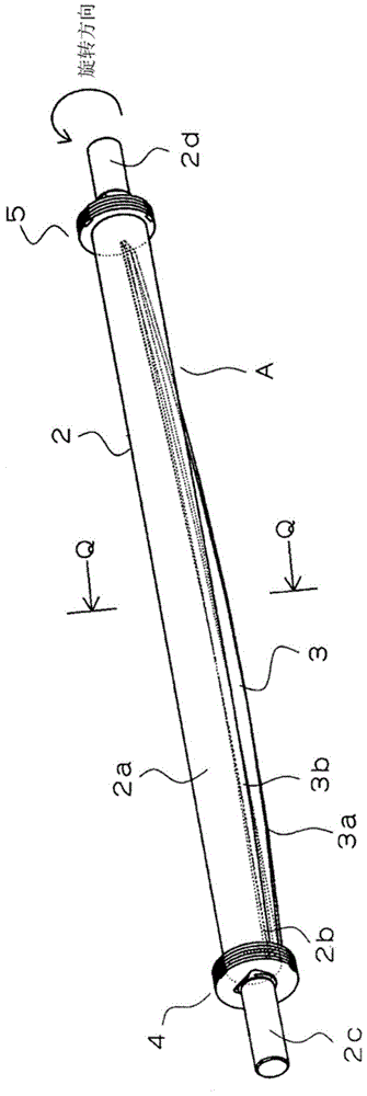
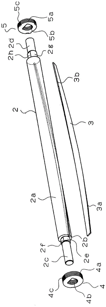
[0040] The rotary knife of the present invention is a rotary knife suitable for sheet cutting, and is a rotary knife in which a blade made of a strip material extends in the longitudinal direction of a bar-shaped shank having a rotation axis.

[0041] In the case of applying a plate material to the blade of a rotary knife as in the prior art, it is necessary to have the simplification and high precision of the assembly with the handle, and the necessary and sufficient mechanical strength as the blade, so that the posture of the blade can be accurately maintained and the Make high-quality cuts. Therefore, it is important that the sheet is not easily lifted from the handle and that the sheet is not only deformed not only plastically but also elastically when fitted to the handle.

[0042] On the basis of fully considering these points, the rotary knife application of the present invention has the strip-shaped material with the above-mentioned special properties that is good flex...


PUM


Abstract

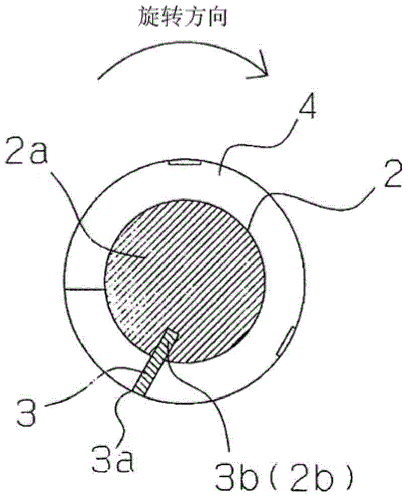
The utility model provides a rotary knife and a rotary cutting device. The rotary knife is formed by a component which can form a blade easily with high precision, a spiral angle for forming the spiral shape of the blade can be easily enlarged and / or the spiral radius is easily reduced, and the component for forming the blade does not need to deform in the width direction when the component is installed with a handle. According to the rotary knife, the blade extends in the length direction of the handle on the periphery of the rod-shaped handle with a spiral shaft, a strip-shaped material for forming the blade forms a spiral shape relative to the length direction of the handle and forms a bow shape bent in the width direction when extending smoothly, one side of the bow shape of the strip-shaped material is assembled on the handle, and the blade is formed on the other side of the bow shape of the strip-shaped material.

Description

technical field [0001] The present invention relates to a rotary knife and a manufacturing method thereof. The rotary knife is mainly used for cutting sheets, and is used in various equipment such as copiers, printers, and ticket vending machines, such as strips, rolls, or Various sheets of paper, film, stickers, labels, etc. of a certain shape are cut to arbitrary lengths. In addition, the present invention also relates to a rotary cutting device using the rotary knife. Background technique [0002] In the past, in the rotary cutting equipment (sheet cutting equipment) that cuts the above-mentioned various sheets by the engagement between the rotary knife (Japanese: ロータリ刀, 回転刀) and the fixed knife (Japanese: Fixed blade), it can often be seen There are rotary knives in which a shank and blade are integrally formed by cutting (Patent Document 1), and rotary knives in which separately formed shanks and blades are integrally fixed (Patent Documents 2 and 3). [0003] For exa...

Claims


Application Information

Patent Timeline
Patent Type & Authority Patents(China)
IPC IPC(8): B26D1/12B26D1/38B65H35/08
Inventor 富永修桥本秀一
Owner HITACHI METALS PRECISION LTD
Learn More