Luggage conveyor belt system
A technology for conveyor belts and luggage, which is applied in the field of airport ground transportation transmission equipment and luggage conveyor belt systems. It can solve the problems of high friction between the belt and the deviation mechanism, uneven luggage load, and low work efficiency, and achieve an improved level and quality. , Reduce maintenance and repair costs, and facilitate operation
- Summary
- Abstract
- Description
- Claims
- Application Information
AI Technical Summary
Problems solved by technology
Method used
Image
Examples
Embodiment 1
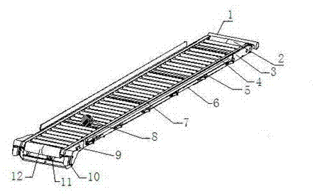
[0021] Example 1: Such as figure 1 , figure 2 , image 3 , as shown, a baggage conveyor belt system, the conveyor belt system includes a conveyor belt body, a driving roller assembly 12 and a driven roller assembly 2 arranged at both ends of the conveyor belt body, and a belt 8 running through the entire system, the baggage conveyor belt system It also includes a belt tensioning mechanism 11, a steering roller 9, and a deviation correction system 6. The tensioning mechanism 11, the steering roller 9, and a deviation correction system 6 are all arranged on the driving roller assembly 12 and the driven roller assembly. between 2. The overall structure of the conveyor belt system is simple, the cost is low, and due to the omission of structural components such as sprockets, the failure rate is low, the maintenance cost is greatly reduced, and it is convenient for large-scale popularization and use.
Embodiment 2
[0022] Example 2: Such as figure 1 , figure 2 , image 3 , as shown, as an improvement of the present invention, the conveyor belt body includes a conveyor frame 3, idler rollers 4 arranged on the conveyor frame, and movable guardrails 5 and guard plates 7 at both ends of the conveyor frame. The rest of the structures and advantages are exactly the same as in Embodiment 1.
Embodiment 3
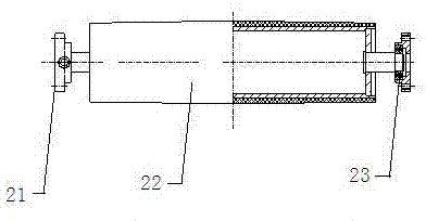
[0023] Example 3: Such as figure 1 , figure 2 , image 3 , Figure 4 , Figure 5 As shown, as an improvement of the present invention, the driving roller assembly 12 includes a driving motor 31, a roller 32 connected to the driving motor, and also includes a self-aligning bearing 33 and a support seat for fixing the self-aligning bearing 33 34. Since the self-aligning bearing 33 is provided, the coaxiality between the driving motor 31 and the roller 32 is ensured, that is, the output shaft of the driving motor is coaxial with the connecting shaft of the driving roller, because the driving motor can be directly connected with the driving roller, The sprocket, which is indispensable in the prior art, is omitted, which not only reduces the cost, but also directly drives the driving roller to work because the driving motor is directly connected with the driving roller, avoiding the problem of out-of-synchronization, and reducing maintenance and repair costs ,Improved work ...
PUM
 Abstract
Description
Claims
Application Information
 - R&D
- Intellectual Property
- Life Sciences
- Materials
- Tech Scout
- Unparalleled Data Quality
- Higher Quality Content
- 60% Fewer Hallucinations
Browse by: Latest US Patents, China's latest patents, Technical Efficacy Thesaurus, Application Domain, Technology Topic, Popular Technical Reports.
© 2025 PatSnap. All rights reserved.Legal|Privacy policy|Modern Slavery Act Transparency Statement|Sitemap|About US| Contact US: help@patsnap.com


