Ground friction drive rotating platform for bumper conveying

A friction drive and bumper technology, applied in the field of conveyors, can solve the problems of short bumper trolley pitch, unusable switch structure, dense friction drive layout, etc., and achieves the effects of ingenious structure, low manufacturing cost and space saving.

Active Publication Date: 2014-03-26
MIRACLE AUTOMATION ENG CO LTD
7 Cites 3 Cited by

AI-Extracted Technical Summary

Problems solved by technology

In the automobile bumper conveying line, due to the short pitch of the trolleys conveying the bumper and the dens...

Abstract

The invention relates to a ground friction drive rotating platform for bumper conveying. The ground friction drive rotating platform comprises a friction drive, an air cylinder component, a rotating shaft component, a rotating disc, a rotating rail and a bottom holder. The rotating disc is supported and mounted on the bottom holder through the rotating shaft component. The friction drive and the rotating rail are fixed to the rotating disc, and the friction drive is arranged beside the rotating rail. The air cylinder component is arranged under the rotating disc, a cylinder body of the air cylinder component is fixed to the bottom holder, and a piston rod end of the air cylinder component is hinged with the rotating disc. The ground friction drive rotating platform has skillful, compact and reasonable structure, is low in manufacturing cost, flexible in turn and space saving, and is capable of realizing distribution of a conveying line within a limited space.

Application Domain

Conveyor parts

Technology Topic

PhysicsRotational axis +6

Image

  • Ground friction drive rotating platform for bumper conveying
  • Ground friction drive rotating platform for bumper conveying
  • Ground friction drive rotating platform for bumper conveying

Examples

  • Experimental program(1)

Example Embodiment

[0012] The present invention will be further described below in conjunction with specific drawings and embodiments.
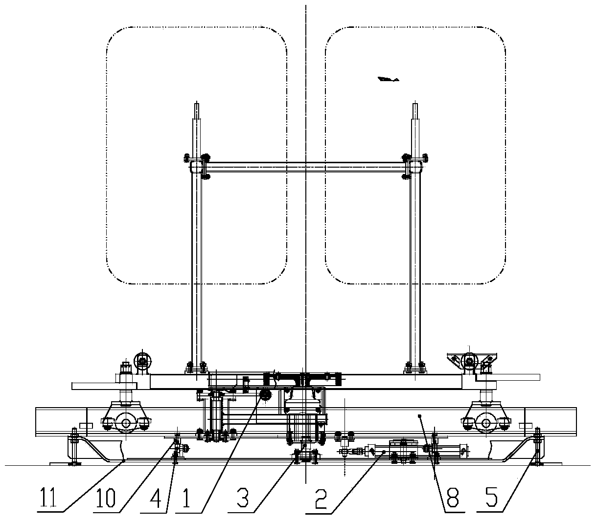
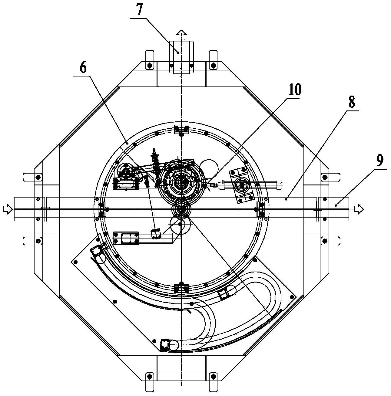
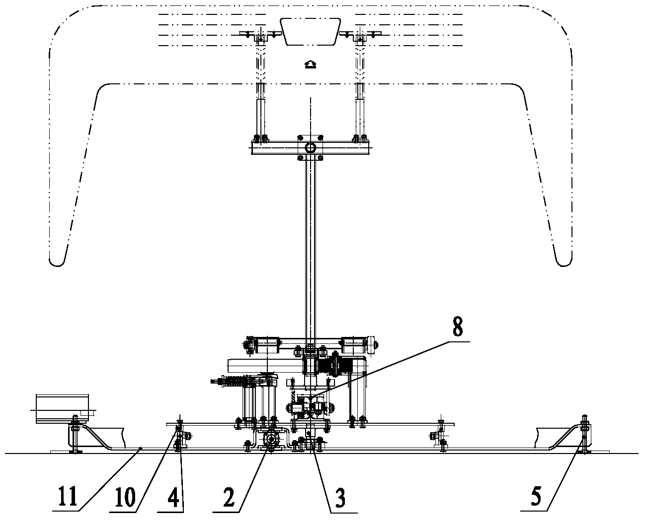
[0013] As shown in the figure: the bumper ground friction drive rotary table of the present invention is mainly composed of friction drive 1, cylinder assembly 2, rotating shaft assembly 3, roller assembly 4, adjusting foot 5, rotating disc 6, rotating track 8, rotating guide rail 10. And the bottom fixing frame 11 and other parts.
[0014] As shown in the figure, the rotating disk 6 is supported and installed on the bottom fixing frame 11 through the rotating shaft assembly 3; the friction drive 1 and the fixed track 8 are fixed on the rotating disk 6, and the friction drive 1 is arranged beside the fixed track 8; The cylinder assembly 2 is arranged under the rotating disk 6, the cylinder body of the cylinder assembly 2 is fixed on the bottom fixing frame 11, and the piston rod end of the cylinder assembly 2 is connected to the rotating disk 6 through internal thread self-lubricating rod end joint bearings and shaft welding parts. connection. A circular rotating guide rail 10 is provided at the bottom of the rotating disk 6, a number of roller assemblies 3 arranged in a circumferential direction are installed on the bottom fixing frame 11, and the rotating guide rail 10 is supported by the roller assemblies 3.
[0015] Such as figure 1 As shown, the bottom fixing frame 11 is provided with an adjusting foot 5, which can be used to adjust the level of the friction drive 1 rotating table of the present invention.
[0016] The specific application situation of the present invention is as follows:
[0017] At the beginning, the end of the fixed rail 8 on the rotating disk 6 is butted with the second fixed rail 9. When the trolley enters the rotating table, the travel switch is triggered to send a signal, and the trolley stops on the fixed rail 8 of the rotating disk 6 at this time; Cylinder assembly 2 starts, pushes the rotating disk 6 and the trolley on the rotating disk 6 and the friction drive 1 stops after rotating 90°. After the rotating disk 6 rotates in place, the switch signal is triggered to start the friction drive 1 and the end of the fixed track 8 is The first fixed track 7 is docked, the friction drive 1 drives the trolley out of the rotating disc 6 to the first fixed track 7, and triggers the switch signal, the cylinder assembly 2 starts again, pulls the rotating disc 6 to rotate 90° in reverse and returns to the original Position, at this point a complete cycle ends.

PUM

no PUM

Description & Claims & Application Information

We can also present the details of the Description, Claims and Application information to help users get a comprehensive understanding of the technical details of the patent, such as background art, summary of invention, brief description of drawings, description of embodiments, and other original content. On the other hand, users can also determine the specific scope of protection of the technology through the list of claims; as well as understand the changes in the life cycle of the technology with the presentation of the patent timeline. Login to view more.

Similar technology patents

Flue dedusting device

Owner:TAICANG CENTURY BRIDGE IND & COMMERCIAL OFFICE

Multi-station aluminum profile drilling machine

Owner:嘉兴裕盛精密机械有限公司

Classification and recommendation of technical efficacy words

  • low manufacturing cost
  • ingenious structure

Exercise equipment

InactiveUS6942605B1low manufacturing costlow price of sale
Owner:SUKHOVITSKY FELIKS

Compliance partitioning in testing of integrated circuits

InactiveUS20080061808A1low manufacturing costgood impedance control
Owner:INNOCONNEX

Inkjet recording apparatus

InactiveUS20050237352A1low manufacturing costfine image quality
Owner:KONICA MINOLTA MEDICAL & GRAPHICS INC
Why Eureka
Try Eureka