
Rotor type car dumper

A dumper and rotor-type technology, which is applied in the direction of mechanical equipment, loading/unloading, and fluid pressure actuating devices, can solve the problems of accelerated hydraulic pipeline joint loosening, increased hydraulic failure rate, and line insulation wear, etc., to reduce oil leakage phenomenon, improve operating efficiency, and reduce maintenance time

Active Publication Date: 2014-03-26
攀钢集团西昌钢钒有限公司
View PDF6 Cites 2 Cited by
  • Summary
  • Abstract
  • Description
  • Claims
  • Application Information

AI Technical Summary

Problems solved by technology

In addition, when dumping is performed, a lot of dust will be generated, resulting in the hydraulic pump station 6 and hydraulic valve station 2, as well as various hydraulic components and pipelines, etc. being easily affected, and more dust will accumulate on their surfaces
[0004] In the dumping operation process, the vibrator 3 on the car device 4 will vibrate when turning forward to about 145°, and stop when turning back to 130°, resulting in a vibration time of about 8 seconds. The permanent deformation of the sealing element in the joint is accelerated, and the pre-tightening force of the joint is reduced to cause loosening, which results in frequent oil leakage of the hydraulic pipe joint in the body, and also causes other hydraulic failures
[0005] When a fault occurs in the hydraulic valve station installed on the body, it is necessary to clean the dust accumulated on the box of the hydraulic valve station and open the closed box cover before the fault can be judged and eliminated. The entire fault handling process takes a long time
In addition, when dealing with hydraulic faults in the main body, since a large amount of dust is adhered to the equipment to be repaired, it will fall and disperse when there is a slight vibration. If the material enters the hydraulic system being repaired, it will cause secondary pollution, resulting in a significant hydraulic failure rate. increase
In addition, since the hydraulic valve station is close to the vibration source (that is, the vibrator 3), the loosening of the hydraulic pipeline joints in this part is further accelerated, causing a series of oil leakage and other failures
In addition, there are 8 electrical signals and control elements in the hydraulic valve station connected to the electrical room on the ground through moving cables, and the vibration in the main body will also cause loosening of electrical connectors, wear and tear of line insulation, etc.
When diagnosing and eliminating electrical faults, it is also necessary to clean the accumulated material on the box of the hydraulic valve station and open the closed box cover to perform fault judgment and troubleshooting. Working efficiency of rotor dumper

Method used


Image

  • Rotor type car dumper
  • Rotor type car dumper
  • Rotor type car dumper

Examples


Embodiment Construction

[0022] In order to enable those skilled in the art to better understand the present invention, specific embodiments of the present invention will be described in detail below in conjunction with the accompanying drawings.

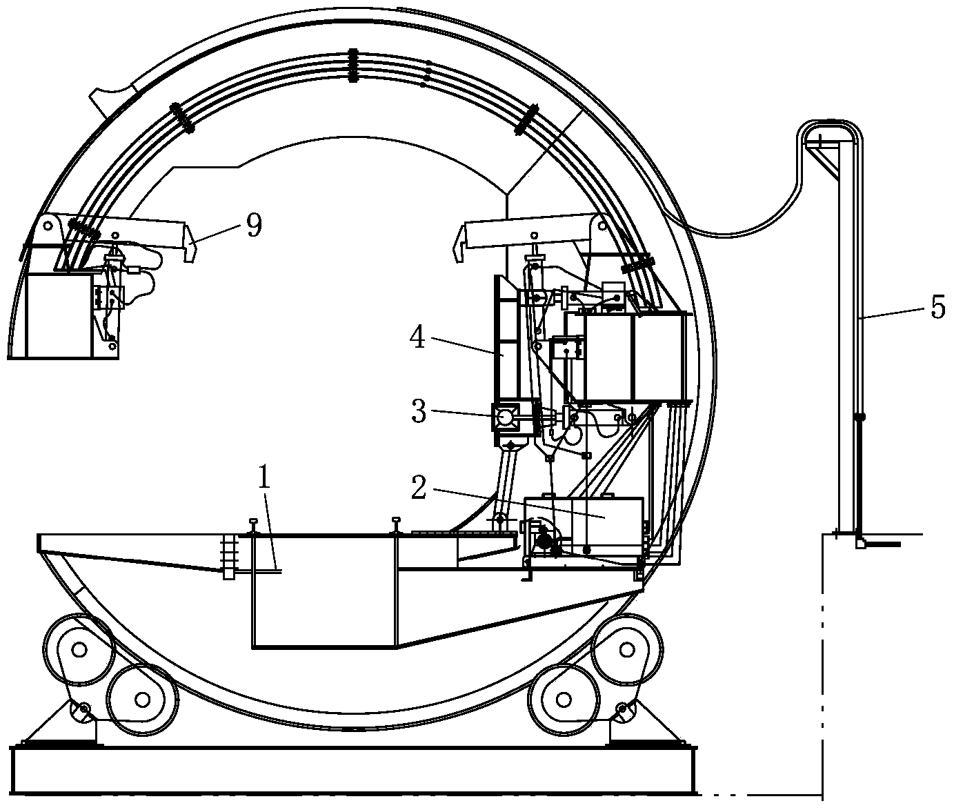
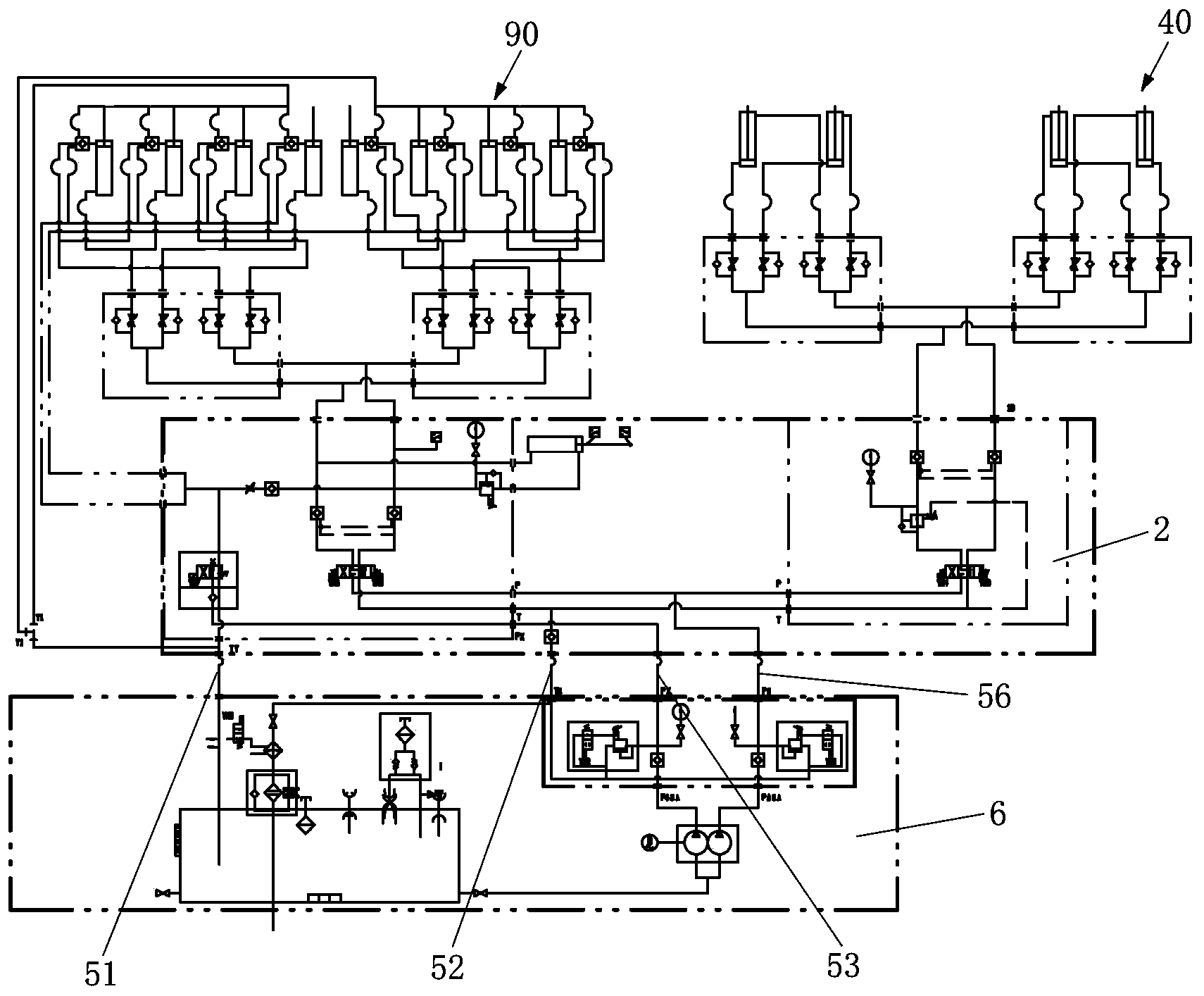
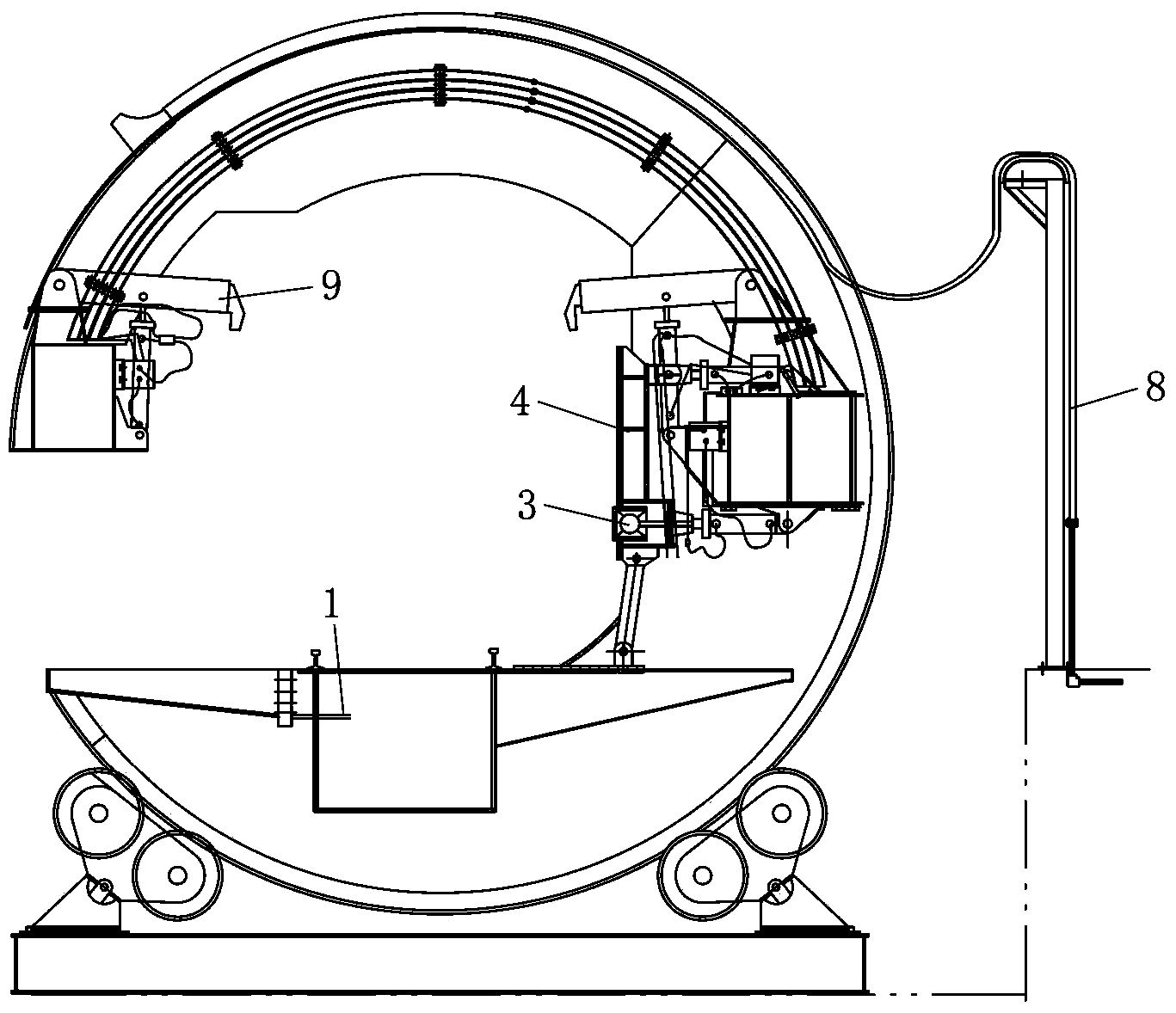
[0023] refer to image 3 with Figure 4 , image 3 is a schematic structural diagram of a rotor dumper according to an embodiment of the present invention, Figure 4 yes figure 1 The hydraulic schematic diagram of the hydraulic system of the rotor dumper shown in .

[0024] According to an embodiment of the present invention, a rotor-type dumper is provided, which includes a body 1, a pressing device 9 installed on the body 1 and a car-resting device 4, which are installed in the body 1 and used to drive the pressing device. Vehicle device 9 and the hydraulic component assembly of vehicle device 4, hydraulic pump station and hydraulic valve station and various hydraulic pipelines. The car pressing device 9 mainly moves up and down to clamp the compartm...


PUM


Abstract

The invention discloses a rotor type car dumper. The rotor type car dumper comprises a body, a car pressing device, a car abutting device, a hydraulic element assembly, a hydraulic pump station, a hydraulic valve station and a hydraulic pipe, wherein the car pressing device and the car abutting device are arranged on the body; the hydraulic element assembly is arranged in the body and is used for hydraulically driving the car pressing device and the car abutting device; the hydraulic pump station and the hydraulic valve station are separated from a main body and are combined to form a secondary hydraulic system; and the secondary hydraulic system is connected with the hydraulic element assembly through the hydraulic pipe. By using the rotor type car dumper, the failure rate is reduced, the repair process on the hydraulic system of the rotor type car dumper is simplified, the repair time is shortened, the reliability of the hydraulic system is improved, and the operation efficiency of the rotor type car dumper is also improved.

Description

technical field [0001] The invention relates to a rotor type dumper. Background technique [0002] The rotor-type dumper is used to unload the gondola car, and mainly includes a main body 1, a vehicle berth device 4 and a car press device 9 installed on the body 1, a vibrator 3 installed on the car berth device 4, a hydraulic pump station, and a hydraulic valve Station 2 and various connecting lines and control elements. At present, for domestic rotor-type dumpers, most of the hydraulic pump station and hydraulic valve station 2 are installed on the body 1 of the rotor-type dumper, or the hydraulic pump station is installed on the ground and only the hydraulic valve station is installed on the ontology, such as figure 1 with figure 2 shown. [0003] For the situation that the hydraulic pump station 6 is installed on the ground and the hydraulic valve station is installed on the body, the hydraulic pump station 6 and the hydraulic valve station 2 are connected through fo...

Claims


Application Information

Patent Timeline
IPC IPC(8): B65G67/48F15B21/08
Inventor 刘垒姜渭
Owner 攀钢集团西昌钢钒有限公司
Learn More