Cloth coiling block transfer trolley

A cloth reel and transfer car technology, which is applied in the direction of winding strips, thin material handling, transportation and packaging, etc., can solve the problems of increased workload, damage to carts and take-up rollers, time-consuming, etc., to reduce damage, The effect of improving service life and improving efficiency

Active Publication Date: 2014-03-26
苏州欧得凯纺织科技有限公司
View PDF5 Cites 5 Cited by
  • Summary
  • Abstract
  • Description
  • Claims
  • Application Information

AI Technical Summary

Problems solved by technology

[0002] As we all know, after the weaving is completed, the cloth is rolled into rolls and divided into packages. The formation of each roll of cloth is usually formed by winding the cloth on it under the drive of the drive device. After a certain amount of cloth is wound , it is necessary to remove the coiled roll and replace it with a new one. However, when removing the coiled roll, it usually relies on manual handling. This method is time-consuming and laborious and cannot meet the requirements The needs of scientific production, in actual use, although the handling of the take-up roller can be completed by means of a cart, it is a pity that the height of the bracket of the existing cart cannot be adjusted. Some brackets are high, and some brackets are low. The cloth roll needs to be manually lifted to a certain height or lowered to a certain height, which affects the efficiency of removing and installing the roll and increases the workload
[0003] Moreover, when the take-up roller of the existing cloth reel is replaced, the new take-up roller needs to be placed on the cart. Generally, the take-up roller is directly thrown onto the cart, which will generate a lot of noise. At the same time, there are varying degrees of damage to the trolley and take-up roller

Method used


Image

  • Cloth coiling block transfer trolley
  • Cloth coiling block transfer trolley

Examples


Embodiment Construction

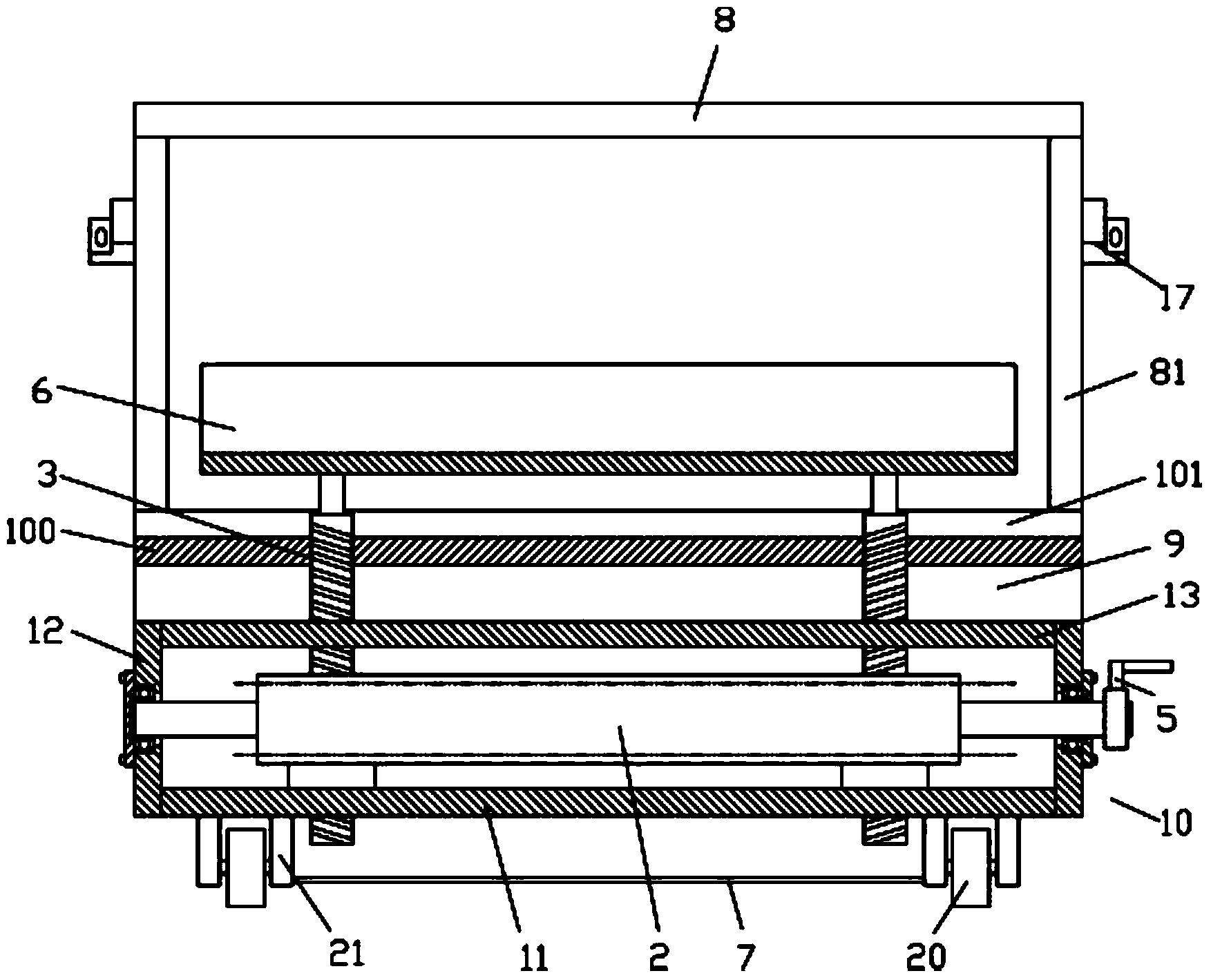
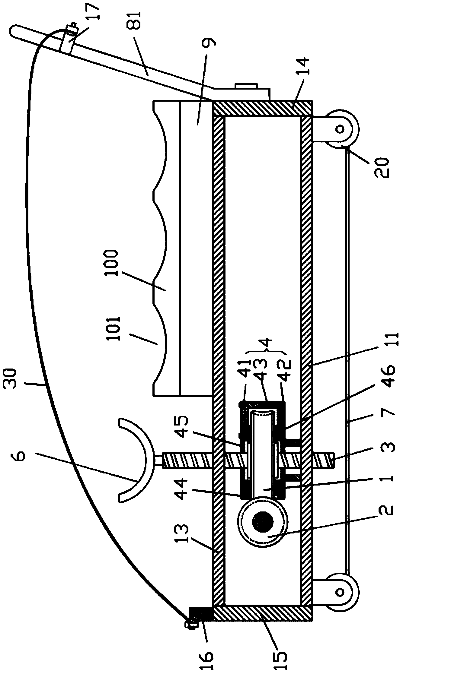
[0016] Example: see Figures 1 to 2 As shown, a cloth reel transfer vehicle includes a bottom box 10 and a wheel assembly 20 fixed on the bottom plate 11 of the bottom box 10. An adjustment assembly is provided in the bottom box 10. The adjustment assembly includes a turbine 1, a worm 2, a screw 3 and the housing 4, the two ends of the worm 2 are hinged on the left and right side panels 12 of the bottom box 10, and one end of the worm 2 protrudes from the left or right side panel 12, on which a rocker 5 is fixed. The structure of the housing 4 is that the upper housing 41 is fixed on the arc-shaped vertical plate 43 formed on the edge of the upper plane of the lower housing 42 to form the housing 4, the side wall of the housing 4 is formed with a gap 44, and the lower housing 42 is formed with a gap 44. The housing 42 is fixed on the upper plane of the base plate 11, the middle part of the upper plane of the lower housing 42 and the middle part of the lower plane of the upper ...


PUM


Abstract

The invention discloses a cloth coiling block transfer trolley comprising a bottom tank and a trolley wheel assembly fixed to a bottom board of the bottom tank, wherein an adjusting assembly is arranged inside the bottom tank and comprises a worm gear, a worm, a lead screw and a shell body; the two ends of the worm are hinged to a left side board and a right side board of the bottom tank; one end of the worm extends out of the left side board or the right side board; a crank is fixed to the worm; one side of the worm gear extends out of a notch and is meshed with the worm; the upper portion and the lower portion of the lead screw are connected to an upper top board and the bottom board of the bottom tank in a screwed mode; the middle of the lead screw is inserted into and sleeved with the shell body and two annular sliding blocks and is connected into a center screw hole of the worm gear in a screwed mode; the top end of the lead screw extends out of the upper top board and is fixed to the bottom face of a bracket; the bottom end of the lead screw extends out of the bottom board. By means of the cloth coiling block transfer trolley, the bracket can be adjusted in a fine mode to meet the heights of take-up rollers of different take-up devices, a cloth coiling block removing device can be placed on the bracket to be conveyed conveniently, and meanwhile the cloth coiling block transfer trolley has the buffering function so as to lower the noise generated when the take-up rollers are thrown onto a coiling block placement block and reduce damage.

Description

Technical field: [0001] The invention relates to the technical field of textile equipment, in particular to a textile fabric reel transfer vehicle. Background technique: [0002] As we all know, after the weaving is completed, the cloth is rolled into rolls and divided into packages. The formation of each roll of cloth is usually formed by winding the cloth on it under the drive of the drive device. After a certain amount of cloth is wound , it is necessary to remove the coiled roll and replace it with a new one. However, when removing the coiled roll, it usually relies on manual handling. This method is time-consuming and laborious and cannot meet the requirements The needs of scientific production, in actual use, although the handling of the take-up roller can be completed by means of a cart, it is a pity that the height of the bracket of the existing cart cannot be adjusted. Some brackets are high, and some brackets are low. The cloth reel needs to be manually lifted to ...

Claims


Application Information

Patent Timeline
Patent Type & Authority Applications(China)
IPC IPC(8): B65H19/30
Inventor 付淑珍
Owner 苏州欧得凯纺织科技有限公司
Why Eureka
Try Eureka