Walling method and walling device

A technology for building walls and equipment, applied in the field of building walls, can solve the problems of inability to fully control the flatness and verticality of walls, high labor intensity, low construction efficiency, etc. , the effect of high work efficiency

Active Publication Date: 2014-03-26
赵路航
View PDF5 Cites 8 Cited by
  • Summary
  • Abstract
  • Description
  • Claims
  • Application Information

AI Technical Summary

Problems solved by technology

[0003] First, for builders, building wall materials such as bricks and blocks require factory production, site storage, loading and unloading, pulling, transporting upstairs, masonry installation and other operations, as well as operations such as hanging nets and plastering. The links are all completed manually, with high labor intensity and low construction efficiency, and the quality of the walls cannot be guaranteed. The walls are prone to cracks, hollowing, and delamination, which will bring huge consumption of funds to the construction industry. Influencing the field of architecture to varying degrees
At the construction site of the wall, a lot of manual work is required, which is not only labor-intensive and time-consuming, but also a large number of damaged and undamaged wall materials are piled up everywhere on the construction site, the construction safety is poor, and a large amount of construction waste is generated.
[0004] Second, for manufacturers, the production of fly ash aerated bricks, ceramsite blocks, gypsum porous lightweight bricks, partition boards and other wall materials requires a large number of factories, sites, production workshops and large-scale brick-making equipment investment, and generate a lot of labor costs
[0005] Third, the quality of the wall cannot be guaranteed. Traditional wall building, plastering and other links require manual construction of formwork and support all over the wall. Not only is the efficiency low, but also limited by the construction characteristics of the existing formwork, the entire wall must be poured at one time. When the slurry-like wall material is used, the slurry-like wall material of the entire wall will exert great pressure on the formwork. Therefore, it is unavoidable that due to the insufficient support of the formwork, the phenomenon of mold running and oar leakage, and the inability to fully control the pouring The flatness and verticality of the wall are also historical problems that plague the construction industry

Method used


Image

  • Walling method and walling device
  • Walling method and walling device
  • Walling method and walling device

Examples


Embodiment 1

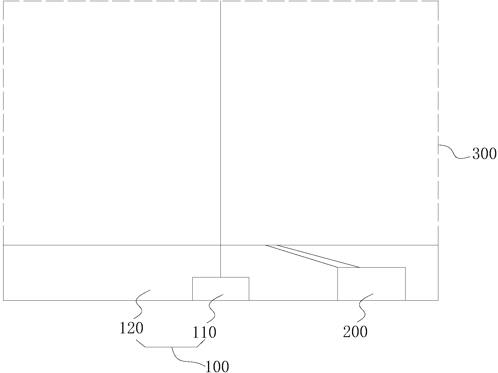
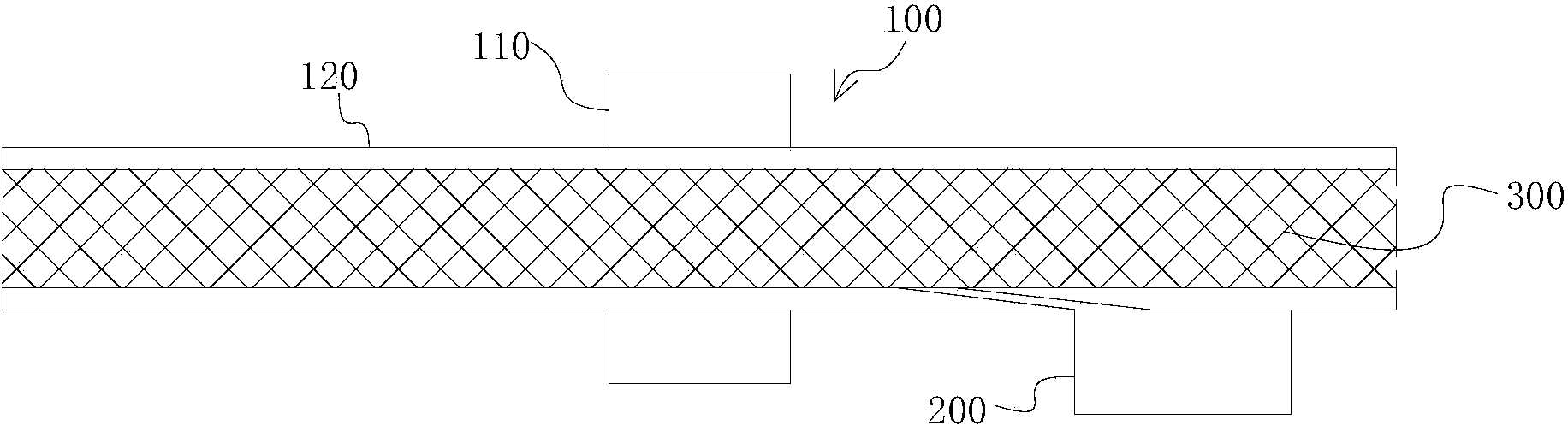
[0053] see Figure 1 ~ Figure 2 , this embodiment discloses a wall-building device, which includes a formwork unit 100 and a pouring unit 200 .

[0054] The template unit 100 includes a driving mechanism 110 and two templates 120 arranged oppositely, wherein: the gap between the two templates 120 is used for pouring slurry wall materials, and the height of the template 120 is smaller than the height of the wall body 300 to be poured. Generally, it is set at a height of 20-50 cm, so as to prevent excessive pressure of one-time poured slurry wall material from causing mold run and slurry leakage. The wall body 300 to be poured is as follows: figure 1 Shown in the dotted line; the width of the template 120 is equal to the width of the wall 300 to be poured, so as to span the entire wall width, and then realize the purpose of a single template 120 without joints; the driving mechanism 110 is used for periodic or continuous The two formworks 120 are lifted.

[0055] The pouring u...

Embodiment 2

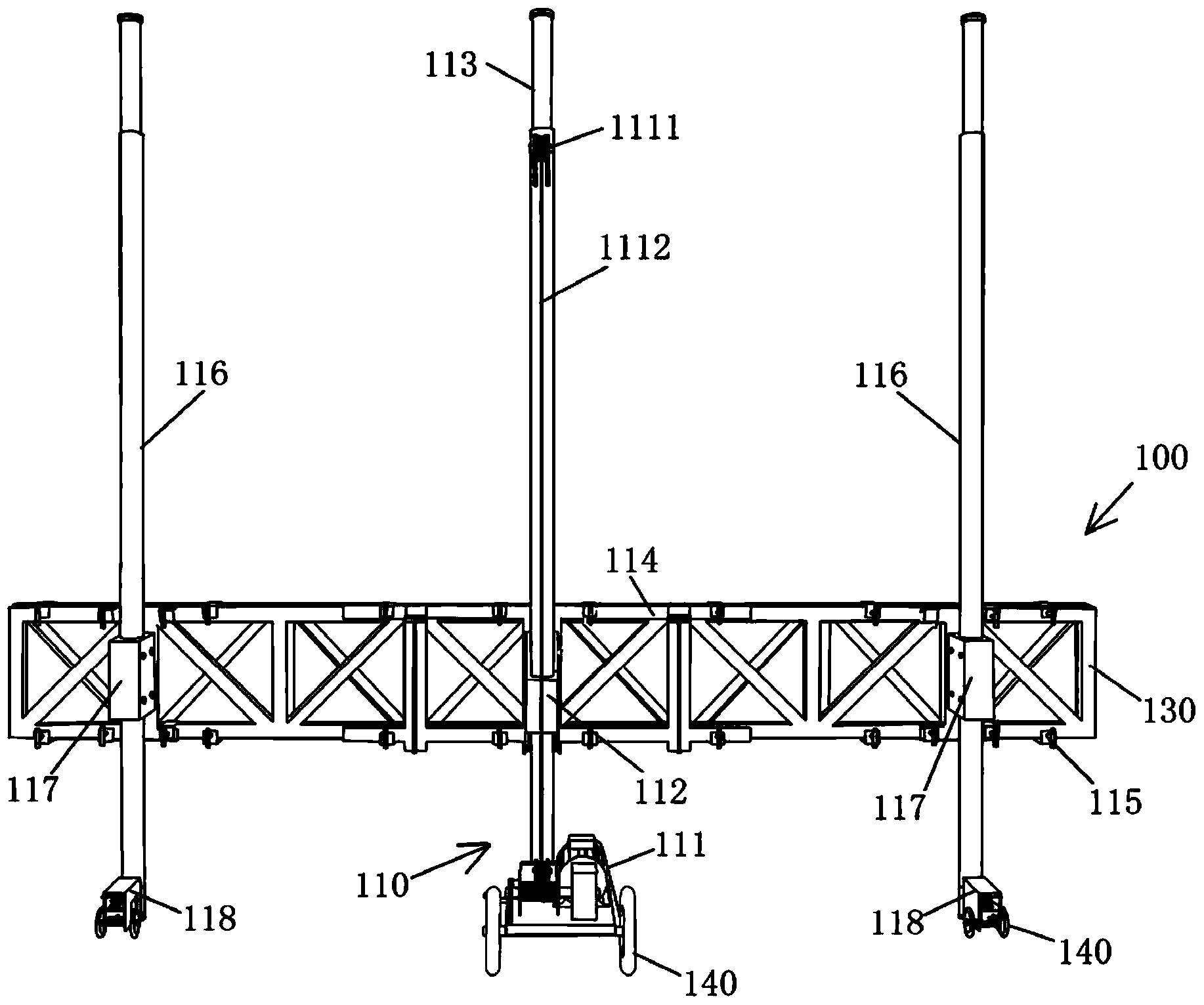
[0058] see Figure 3 ~ Figure 4 , this embodiment also discloses a wall-building equipment, which is a further improvement on the wall-building equipment based on the first embodiment, and the technical solution disclosed in the first embodiment also belongs to this embodiment. Example 1 The disclosed technical solution will not be described again.

[0059] In this embodiment, the template unit 100 is mainly further improved. In order to express the improved technical features more clearly, image 3 and Figure 4 The pour unit is omitted.

[0060] In the present invention, the driving mechanism 110 can adopt various mechanical transmission structures, as long as the template 120 can be lifted. In order to simplify the structure and improve the compactness of the driving structure, in this embodiment, the The driving mechanism 110 is preferably configured to include a hoist 111 , a main slider 112 , a main support column 113 , a lifting claw 114 and a support 130 . Wherein:...


PUM


Abstract

The invention discloses a walling method and a walling device. The walling method includes the steps of respectively arranging formworks on the two sides of a wall to be poured, and installing supports outside the formworks, wherein the heights of the formworks are smaller than the height of the wall to be poured, and the widths of the formworks are equal to the width of the wall to be poured; pouring the position between the formworks on the two sides with a certain number of grout-type wall materials, then stopping pouring, after a certain period of time, lifting the formworks on the two sides to be at certain heights, pouring the position between the formworks on the two sides with a certain number of grout-type wall materials again, then stopping pouring, and repeating lifting and pouring till the whole wall is completely built; or pouring the position between the formworks on the two sides with the grout-type wall materials, and after a certain period of time, starting to continuously lift the formworks and synchronously and continuously pour the position between the formworks with the grout-type wall materials till the whole wall is completely built; after the whole wall is solidified, disassembling the formworks and the supports. The walling device comprises a formwork unit and a pouring unit. The walling method and the walling device are high in walling efficiency, good in quality and free of formwork-moving grout-leakage phenomena.

Description

technical field [0001] The invention relates to the technical field of building walls, in particular to a method for building a non-load-bearing wall and a device for building a non-load-bearing wall. Background technique [0002] At present, for the construction of non-load-bearing walls, the main wall materials are fly ash aerated bricks, ceramsite blocks, gypsum porous lightweight bricks, partition boards, etc. The construction methods of such walls need to rely on artificial Complete masonry; or, it is formed by pouring slurry wall materials, which needs to be manually installed and supported by multiple vertically arranged formworks all over the wall, and then the slurry wall materials injected into the entire wall at one time are solidified . Traditional construction methods have at least the following defects: [0003] First, for builders, building wall materials such as bricks and blocks require factory production, site storage, loading and unloading, pulling, tran...

Claims


Application Information

Patent Timeline
Patent Type & Authority Applications(China)
IPC IPC(8): E04G21/02E04G11/22
Inventor 赵润琪赵路航
Owner 赵路航
Why Eureka
Try Eureka