
Method of Reinforcement of Structure with Reinforced Concrete Frame with Ductile Column Energy Dissipator

A technology of reinforced concrete and reinforced structure, applied in building components, building structure, building maintenance, etc., can solve the problems of increasing the energy dissipation and shock absorption effect of the structure, lack of connection between old and new concrete, unable to form a whole, etc., so as to improve the bearing capacity. , flexible layout, small effect of using functions

Inactive Publication Date: 2015-12-30
BEIJING UNIV OF TECH
View PDF6 Cites 1 Cited by
  • Summary
  • Abstract
  • Description
  • Claims
  • Application Information

AI Technical Summary

Problems solved by technology

The combination of the existing structure and the external high-ductility reinforced concrete energy-dissipating column frame not only increases the energy-dissipating and shock-absorbing effect of the structure, but also solves the problems that the old and new concrete lack connections and cannot form a whole, and the stress-strain lag problem

Method used


Image

  • Method of Reinforcement of Structure with Reinforced Concrete Frame with Ductile Column Energy Dissipator
  • Method of Reinforcement of Structure with Reinforced Concrete Frame with Ductile Column Energy Dissipator
  • Method of Reinforcement of Structure with Reinforced Concrete Frame with Ductile Column Energy Dissipator

Examples


Embodiment 1

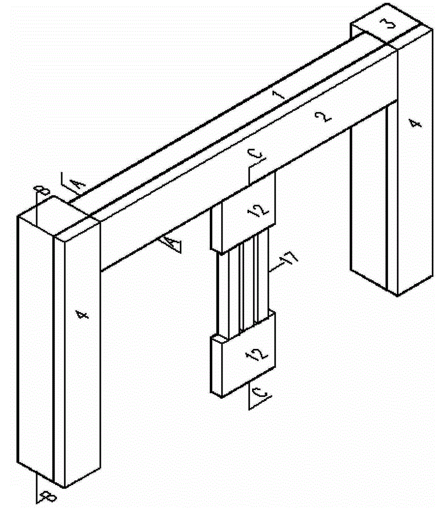
[0027] The specific construction method, taking the application in the frame beam as an example:

[0028] a. Design and manufacture

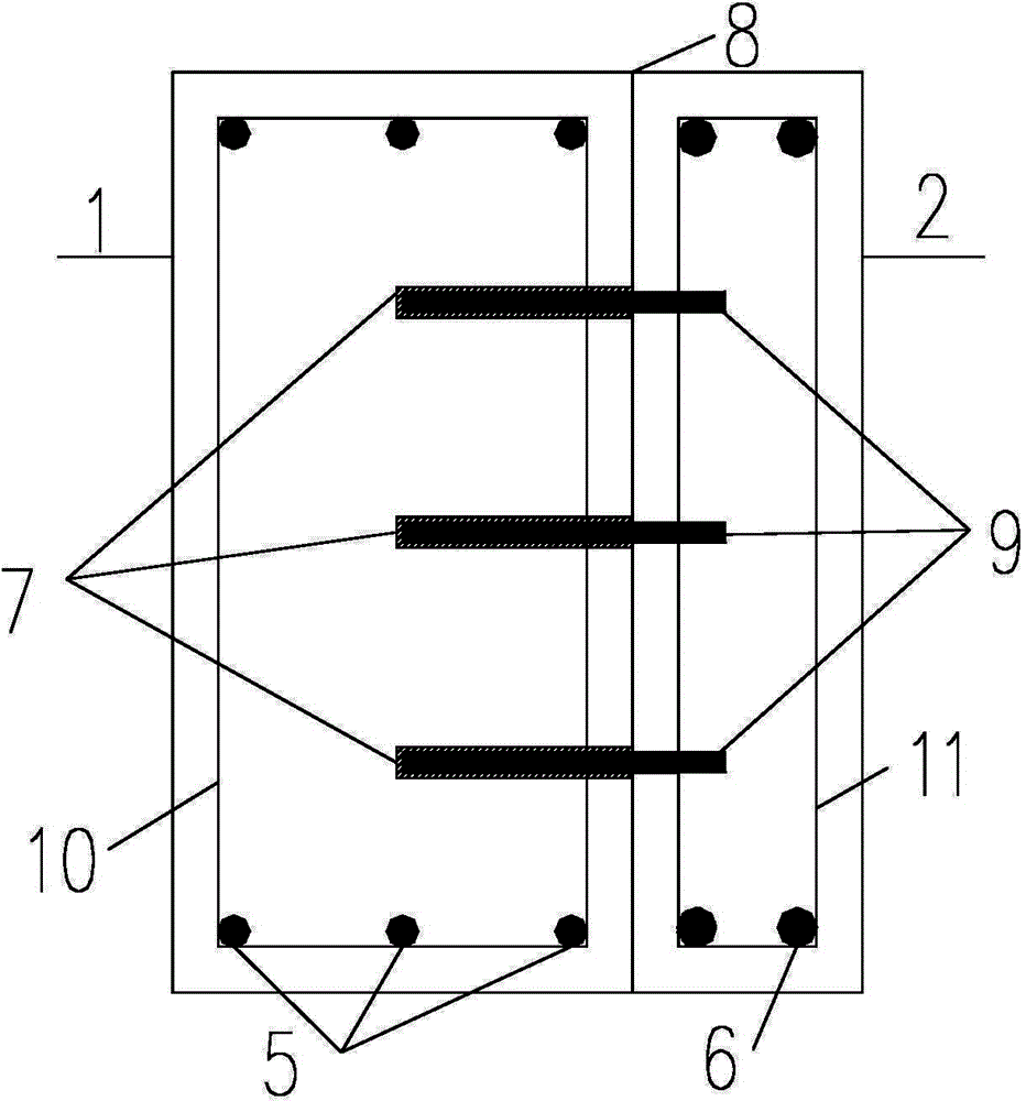
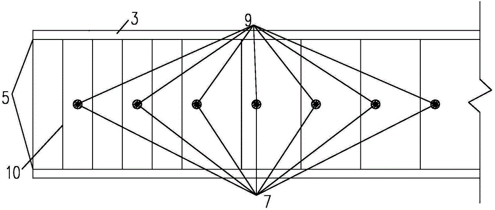
[0029] According to the section size of the original reinforced concrete frame beam 1, the newly added reinforced concrete frame beam 2 section is designed. According to the section and height of the newly added reinforced concrete frame beam 2, the size and reinforcement of the energy-dissipating column are designed. Select the type of glue for planting bars 7 and the diameter of the anchor bar 9, the depth of bars for planting, the distance between bars for planting, and the diameter of the drilled hole. Clean the concrete gouges on the surface of the original reinforced concrete frame beam at joint surface 8.

[0030] b.Anchoring

[0031] In the original reinforced concrete frame beam 1, holes are punched on the section along the length direction according to the parameters of the planting bar, the planting bar glue 7 is implanted, and the...


PUM


Abstract

The invention discloses a method for reinforcing structures through a method of externally pasting a reinforced concrete frame with ductility column energy dissipators, and belongs to the field of reinforcement of concrete structures. The reinforced concrete frame with the ductility column energy dissipators is externally pasted on the outer side of an original reinforced concrete frame structure. The intensity grade of the concrete and the intensity grade of the reinforcing steel bars of a newly added frame beam and those of a newly added frame column are higher than those of an original frame beam and those of an original frame column, and the intensity grade difference should not exceed two. The newly added frame beam and the newly added frame column are connected with the original frame beam and the original frame column respectively through an adhesively bonded anchorage mode. The adhesively bonded anchorage mode is achieved through the fact that embedded steel bar glue is implanted by drilling anchor bars to be fixedly connected with original frame concrete. The anchor bars and the newly added frame structure are cast in situ. Each reinforced concrete ductility column energy dissipator comprises a reinforced concrete ductility column and rigid supports at the two ends of the corresponding reinforced concrete ductility column. The intensity grade of the concrete and the intensity grade of the reinforcing steel bars of the reinforced concrete ductility column energy dissipators are identical to those of the newly added frame. The reinforced concrete ductility column energy dissipators and the newly added reinforced concrete beam are integrally cast in situ. The method is quite beneficial to reinforcement effects.

Description

technical field [0001] The invention belongs to the field of concrete structure reinforcement, and in particular relates to a reinforced concrete frame method reinforcement structure with ductile column energy dissipators. Background technique [0002] Reinforced concrete frame structures and bottom frame structures have been widely used in multi-story buildings due to their flexibility in spatial arrangement. Due to the different functions of the bottom frame structure, the structural layout is different, and it is easy to form a structural system with uneven rigidity and rigid top and soft bottom. There may be a serious lack of earthquake resistance, and tilting or collapse will occur during an earthquake, which will cause great obstacles and economic costs to structural repair and disaster relief. [0003] my country's "Code for Design of Reinforcement of Concrete Structures" (GB50367-2006) proposes a variety of reinforcement methods. For example, the method of enlargin...

Claims


Application Information

Patent Timeline
Patent Type & Authority Patents(China)
IPC IPC(8): E04G23/02E04B1/98
Inventor 马华付静杜晓霞陈磊李汉杰李振宝
Owner BEIJING UNIV OF TECH
Learn More