Hydraulic control device, method and system and engineering machine

A hydraulic control system and control equipment technology, applied in mechanical equipment, fluid pressure actuators, servo motors, etc., can solve the problems that the piston speed cannot be kept constant, and it is difficult to accurately control the piston speed and displacement of the oil cylinder, etc.

Active Publication Date: 2014-03-26
HUNAN ZOOMLION INTELLIGENT TECH +1
View PDF9 Cites 9 Cited by
  • Summary
  • Abstract
  • Description
  • Claims
  • Application Information

AI Technical Summary

Problems solved by technology

[0003] However, in the actual application process, this situation often occurs, that is, when the current input to the solenoid valve is constant, the movement speed of the piston cannot be kept constant, so it is difficult to accurately control the speed and displacement of the cylinder piston

Method used


Image

  • Hydraulic control device, method and system and engineering machine
  • Hydraulic control device, method and system and engineering machine
  • Hydraulic control device, method and system and engineering machine

Examples


Embodiment Construction

[0021] Specific embodiments of the present invention will be described in detail below in conjunction with the accompanying drawings. It should be understood that the specific embodiments described here are only used to illustrate and explain the present invention, and are not intended to limit the present invention.

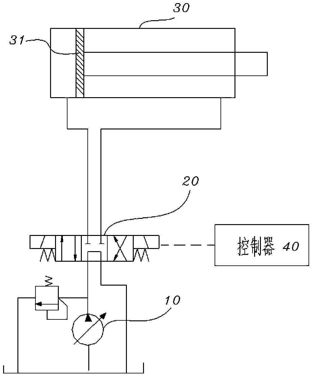
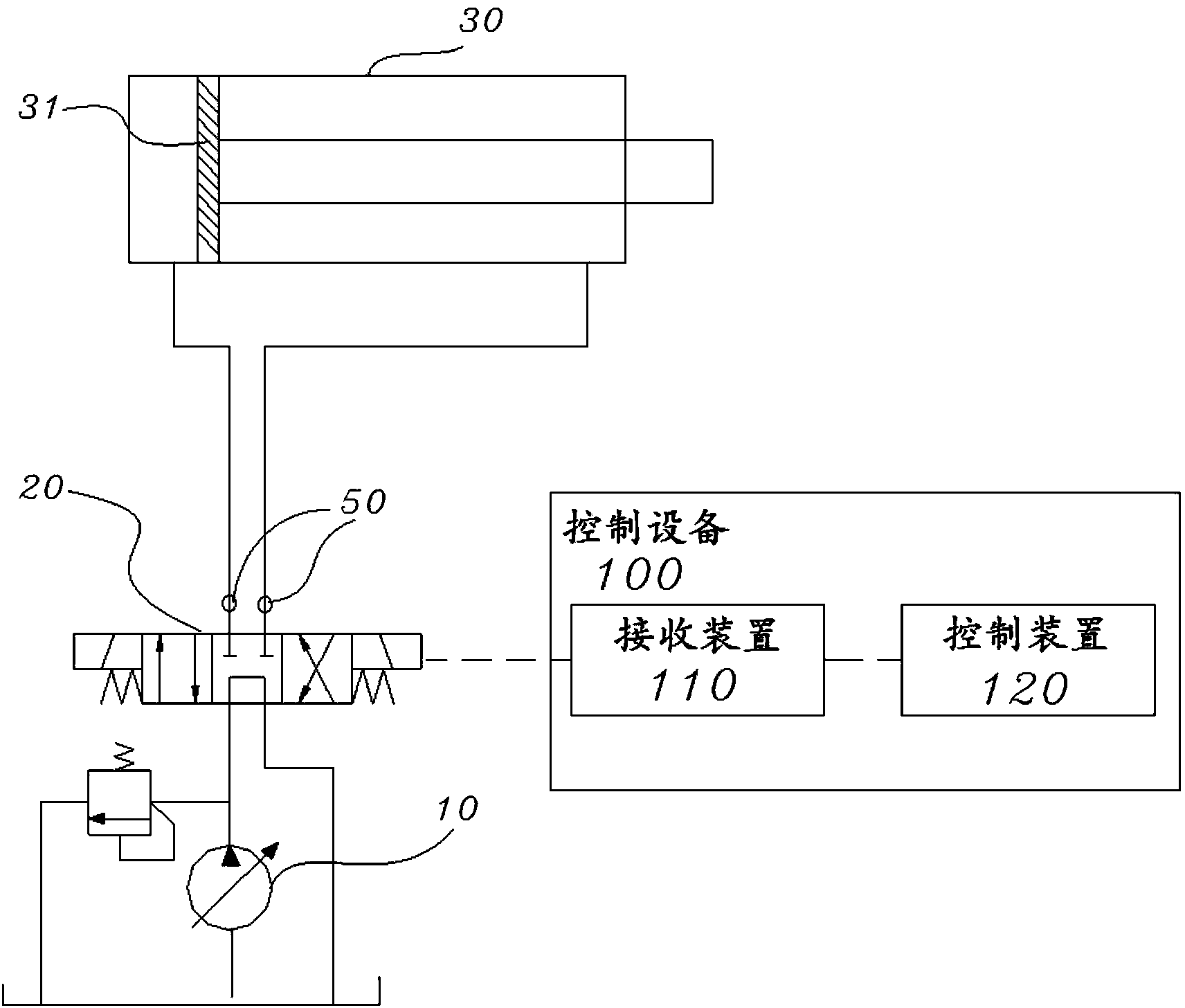
[0022] figure 2 It is a schematic structural diagram of the hydraulic control system provided by the present invention. Such as figure 2 As shown, the hydraulic control system provided by the present invention includes: a temperature detection device for detecting the temperature of the hydraulic oil flowing through the valve port of the solenoid valve; and a hydraulic control device, which includes: a receiving device for receiving the the temperature of the hydraulic oil of the electromagnetic valve and the target moving speed of the piston; and the control device, based on the temperature and the target moving speed, controls the control current applied t...


PUM


Abstract

The invention discloses a hydraulic control device, method and system and an engineering machine. Hydraulic oil driven by a hydraulic pump flows in an oil cylinder through an electromagnetic valve to drive a piston in the oil cylinder to move. The hydraulic control device comprises a receiving device and a control device, wherein the receiving device is used for receiving the temperature of the hydraulic oil flowing through the electromagnetic valve and the target moving speed of the piston, and the control device is used for controlling a control current exerted on the electromagnetic valve based on the temperature and the target moving speed to enable the moving speed of the piston to meet the target moving speed. By means of the technical scheme, accurate control over oil cylinder and piston based on temperature compensation can be achieved to address the influences of different oil temperatures on the circulating flow of a valve opening of the electromagnetic valve.

Description

technical field [0001] The present invention relates to the field of hydraulic control, in particular to a hydraulic control device, a hydraulic control method, a hydraulic control system and construction machinery using the system. Background technique [0002] figure 1 It is a schematic diagram of the structure of the existing hydraulic system. Such as figure 1 As shown, the hydraulic system includes a pump, a solenoid valve, an oil cylinder and a controller. The pump can pump hydraulic oil into the oil cylinder through the solenoid valve, and then drive the piston in the oil cylinder to move. The controller can control the magnitude of the current input to the solenoid valve, thereby controlling the opening of the solenoid valve, and then controlling the flow of hydraulic oil flowing into the oil cylinder, thereby controlling the movement speed of the piston. [0003] However, in the actual application process, this situation often occurs, that is, when the current inp...

Claims


Application Information

Patent Timeline
Patent Type & Authority Applications(China)
IPC IPC(8): F15B11/06F15B11/04
Inventor 赵鑫万梁李志杰
Owner HUNAN ZOOMLION INTELLIGENT TECH
Why Eureka
Try Eureka