Swing device

A technology of swinging device and swinging arm, which is applied in the direction of transmission device, belt/chain/gear, mechanical equipment, etc., can solve the problem of swinging arm with no return, etc., and achieve the effect of simple structure

Inactive Publication Date: 2014-03-26
CHONGQING ZHIRUIDE TECH
View PDF1 Cites 3 Cited by
  • Summary
  • Abstract
  • Description
  • Claims
  • Application Information

AI Technical Summary

Problems solved by technology

[0003] The present invention intends to provide a oscillating device to solve the problem t

Method used


Image

  • Swing device

Examples


Example Embodiment

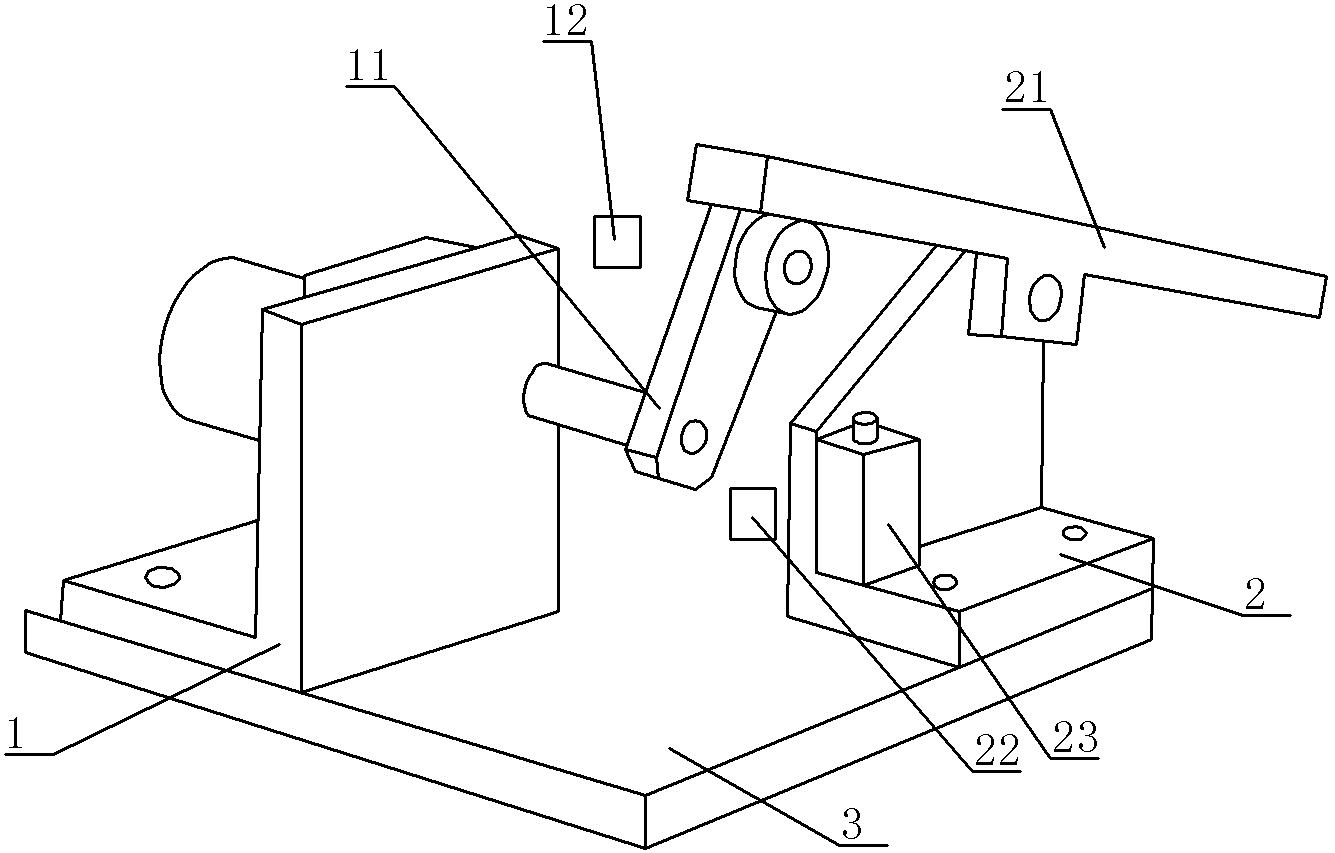
[0009] according to figure 1 As shown, the swing device in the embodiment of the present invention includes a frame 3, and also includes a first fixing plate 1 threadedly connected to the frame 3, a second fixing plate 2 threaded to the frame 3, and a first fixing plate 1 The drive shaft connected to rotation, the rotating arm 11 fixed to the drive shaft, the swing arm 21 hinged to the second fixed plate 2 in the middle, and the stop switch 23 fixed on the second fixed plate 2, the upper end of the swing arm 21 and one end of the rotating arm 11 In contact, the lower end of the swing arm 21 is the working end, and a first limit switch 12 and a second limit switch 22 are provided on the frame 3 near the rotating arm 11.

[0010] What has been described above is only an embodiment of the present invention, and common knowledge such as specific structures and characteristics that are well-known in the solution are not described here. It should be pointed out that for those skilled ...


PUM


Abstract

The invention discloses a swing device to solve the problem that the in prior art, the efficiency is low in the manual thin plate laminating process. The swing device comprises a machine frame and further comprises a first fixed plate connected with the machine frame, a second fixed plate connected with the machine frame, a drive shaft connected with the first fixed plate in a rotating mode, a rotating arm fixed to the drive shaft, a swing arm with the middle hinged to the second fixed plate, and a stopping switch fixed to the second fixed plate. The upper end of the swing arm makes contact with one end of the rotating arm, the lower end of the swing arm is a working end, and a first limiting switch and a second limiting switch are arranged on the portion, close to the rotating arm, of the machine frame. The swing device is simple in structure and capable of enabling the swing arm to freely reciprocate.

Description

technical field [0001] The invention relates to the technical field of reciprocating motion, in particular to a swing device. Background technique [0002] In the existing mechanical transmission device, in order to convert circular motion into reciprocating motion, a coaxial peach-shaped cam is usually set on the rotating shaft: that is, the cam drive uses the protruding part of the peach tip to push out the swing arm, so that The circular motion of the cam drive is converted into the linear motion of the swing arm. Taking a known cam drive (Chinese patent CN89211301.4) as an example, its shortcoming is: after the peach-shaped cam pushes out the swing arm, the swing arm in this device can only There is no reciprocation, and the swing arm cannot automatically reciprocate mechanically. Contents of the invention [0003] The present invention intends to provide an oscillating device to solve the problem that the oscillating arm of the cam transmission device in the prior a...

Claims


Application Information

Patent Timeline
IPC IPC(8): F16H21/40
CPCF16H21/40
Inventor 严米琪
Owner CHONGQING ZHIRUIDE TECH
Why Eureka
Try Eureka