Thermal image analytical control device and thermal image analytical control method

A control device and image analysis technology, applied in image communication, TV, color TV parts, etc., can solve the problems of difficult complicated analysis, reduced reference value of measurement results, inconvenient use, etc.

Inactive Publication Date: 2014-03-26
MISSION INFRARED ELECTRO OPTICS TECH
View PDF8 Cites 3 Cited by
  • Summary
  • Abstract
  • Description
  • Claims
  • Application Information

AI Technical Summary

Problems solved by technology

[0005] And even if the analysis area is set in advance, it is still very inconvenient to use, because it is impossible for the user to Image 6 The analysis area F1 shown intuitively understands the specific analysis parts in the thermal image of the subject, and the analysis is prone to errors
In addition, in the prior art, in order to avoid the influence of the displayed analysis area on the infrared thermal image observation, it is inconvenient to set various analysis areas, and it is not easy to perform complex analysis
[0006] Due to the above reasons, currently users set a simple analysis area based on experience, such as setting the highest temperature to automatically capture in most cases, but this extensive analysis method reduces the reference value of the measurement results when shooting

Method used


Image

  • Thermal image analytical control device and thermal image analytical control method
  • Thermal image analytical control device and thermal image analytical control method
  • Thermal image analytical control device and thermal image analytical control method

Examples


Embodiment 1

[0046] In Embodiment 1, the thermal image device 13 is used as an example of a thermal image analysis control device.

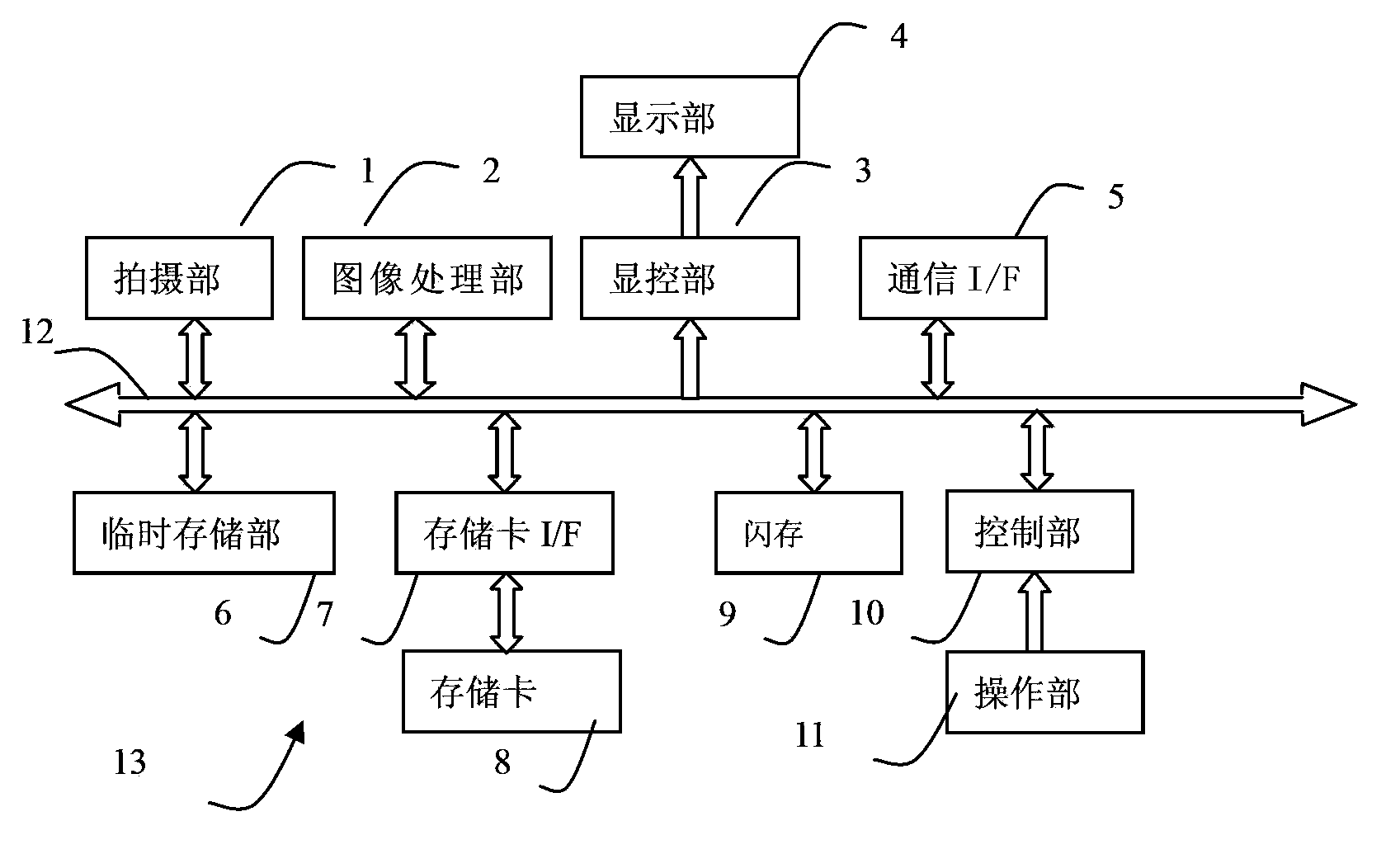
[0047] refer to figure 1 The structure of the thermal imaging device 13 of the first embodiment will be described. figure 1 It is a block diagram of the electrical structure of the thermal imaging device 13 of the embodiment.

[0048] The thermal imaging device 13 has a photographing part 1, an image processing part 2, a display and control part 3, a display part 4, a communication I / F5, a temporary storage part 6, a memory card I / F7, a memory card 8, a flash memory 9, a control part 10, The operation part 11 and the control part 10 are in charge of the overall control of the thermal imaging device 13 by connecting with the above corresponding parts through the control and data bus 12 . The control unit 10 is realized by, for example, a CPU, MPU, SOC, programmable FPGA, or the like.

[0049]The imaging unit 1 is composed of unillustrated optical componen...

Embodiment approach

[0050] The image processing unit 2 is used to perform specified processing on the thermal image data obtained by the shooting unit 1. The processing of the image processing unit 2, such as correction, interpolation, false color, synthesis, compression, decompression, etc., is converted into a suitable display, Handling of data such as recording. The image processing unit 2 is used to perform prescribed processing on the thermal image data captured by the imaging unit 1 to obtain image data of infrared thermal images. For example, the image processing unit 2 performs non-uniformity correction on the thermal image data acquired by the imaging unit 1 , interpolation and other prescribed processing, perform pseudo-color processing on the thermal image data after the prescribed processing, and obtain image data of infrared thermal images; an implementation of pseudo-color processing, for example, according to the range or AD value of thermal image data (AD value) The setting range ...

Embodiment 2

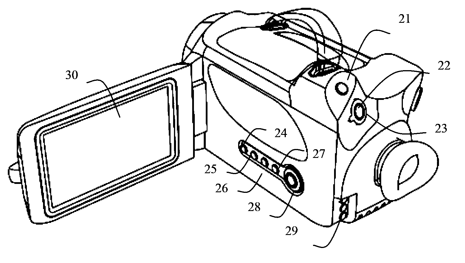
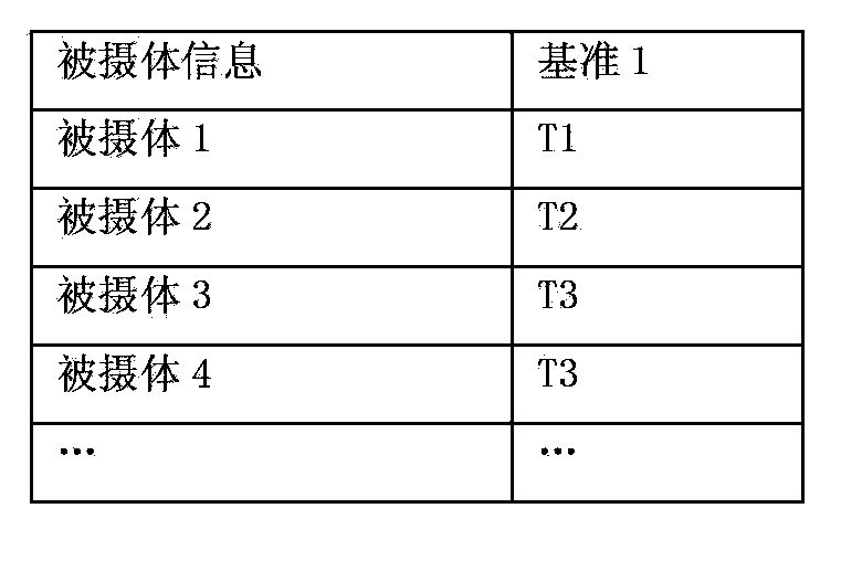
[0220] The control flow of Embodiment 2 will be described in detail below. Embodiment 2 is a thermal imaging device 13 having the same structure as that shown in Embodiment 1. An analysis control program different from that of Embodiment 1 is stored in the flash memory 9. In response to an analysis instruction from a user, the thermal image data will be frozen, displayed and maintained. ; and, also stored as Figure 4 storage contents shown. Different from the operation in Embodiment 1, the user's operation is: press the mode key 25 of the operation part 11 to enter the reference mode, and when analysis is required, press the analysis key 26 to perform analysis and check the analysis results. Also, the user sets the same configuration as in Embodiment 1.

[0221] refer to Figure 23 To illustrate the control flow.

[0222] In step B01, the control unit 10 continuously monitors whether the user selects the reference mode.

[0223] In the standby shooting state, the control...


PUM


Abstract

The invention provides a thermal image analytical control device and a thermal image analytical control method, and relates to thermal image devices, thermal image processing devices and the application field of infrared imaging detection. A thermal image device in the prior art needs to rely on subjective experience of a user to set an analysis area and an analytical model for a photographed object during photographing, the operation is complicated and results of thermal image condition assessment is affected. According to the invention, a reference image reflecting predetermined morphological characteristics of the photographed object is displayed in an infrared thermal image; the reference image is taken as visual reference for photographing a thermal image of the photographed object; and the thermal image of the photographed object is then analyzed through an analysis area corresponding to the reference image and according to an analytical model corresponding to the analysis area to obtain analysis results, wherein the analysis area can be obtained via calculation or processing through the reference image or the like, with accurate position and simple operation. Therefore, an ordinary user can also achieve a good photographing skill level.

Description

technical field [0001] The thermal image analysis control device and thermal image analysis control method of the present invention relate to thermal imaging devices, thermal image processing devices, and the application fields of infrared thermal imaging detection. Background technique [0002] As a well-known technology, the thermal imaging device forms an image by receiving the infrared energy radiation of the subject, and calculates the result of the thermal image analysis according to the analysis area and analysis mode set by the user for the thermal image of the subject. Body thermal image and analysis results to judge the state of the subject. [0003] Among them, the analysis area corresponds to the part that needs to be analyzed in the infrared thermal image, such as a point, line, surface and other area units or a combination of multiple area units; the analysis mode represents the specified analysis based on the thermal image data determined by the analysis area ...

Claims


Application Information

Patent Timeline
Patent Type & Authority Applications(China)
IPC IPC(8): G01J5/10H04N5/232H04N5/33
Inventor 王浩
Owner MISSION INFRARED ELECTRO OPTICS TECH
Why Eureka
Try Eureka