Cathode emission testing apparatus and system for microwave vacuum electronic devices

A cathode emission and testing device technology, applied in vacuum tube testing, measurement/testing in the manufacturing process, etc., can solve the problems of complex cathode installation, difficult control of the distance and parallelism between cathode and anode, and ensuring parallelism of cathode and anode, etc. To achieve the effect of simple structure, improve accuracy and test efficiency

Inactive Publication Date: 2014-03-26
INST OF ELECTRONICS CHINESE ACAD OF SCI
View PDF7 Cites 4 Cited by
  • Summary
  • Abstract
  • Description
  • Claims
  • Application Information

AI Technical Summary

Problems solved by technology

[0005] In these two cathode emission test devices, the distance and parallelism between the cathode and the anode are difficult to control, and can only be roughly controlled by human eyes. It is especially difficult to ensure the parallelism between the cathode and the anode. The test results have a very large impact, because the cathode emission test is based on the theory of ideal planar diodes
In addition, these two test devices are more complicated in terms of cathode installation.

Method used


Image

  • Cathode emission testing apparatus and system for microwave vacuum electronic devices
  • Cathode emission testing apparatus and system for microwave vacuum electronic devices
  • Cathode emission testing apparatus and system for microwave vacuum electronic devices

Examples


Embodiment Construction

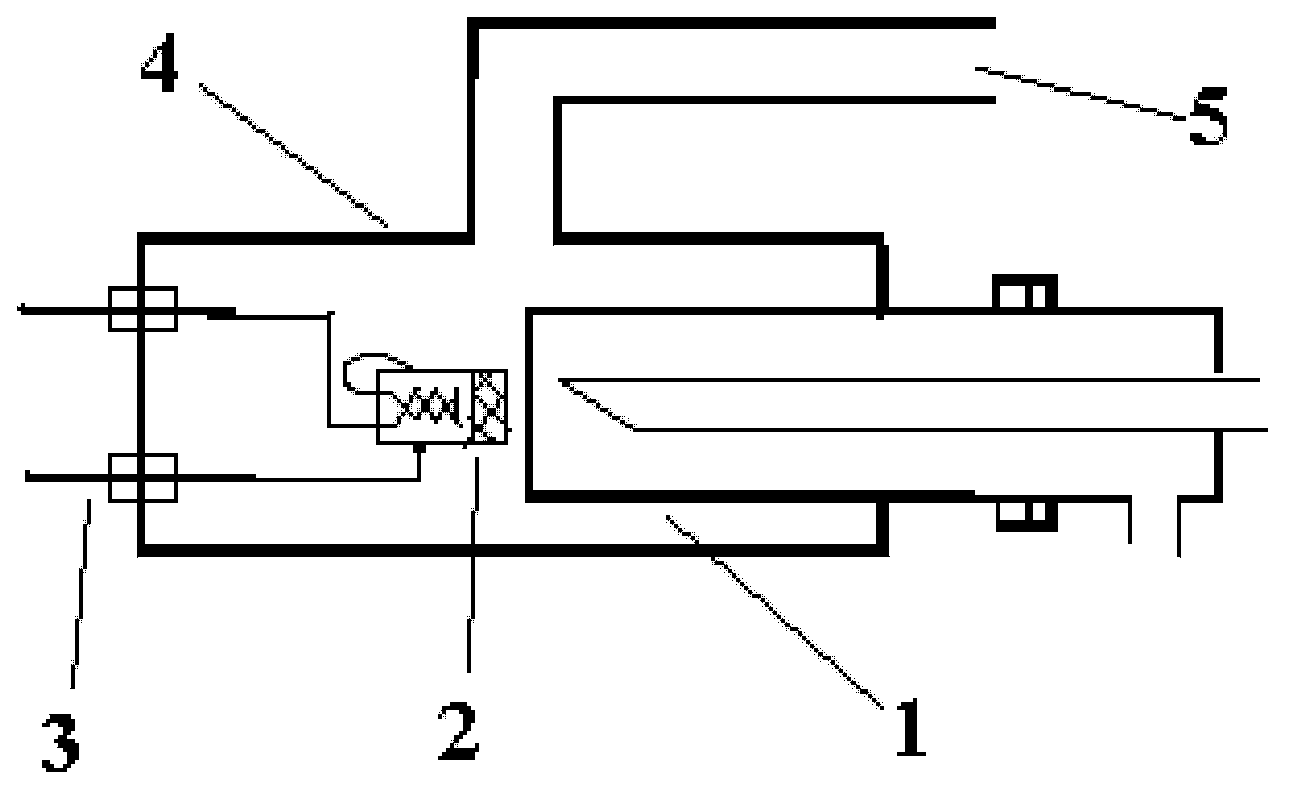
[0027] In order to achieve the above object, the cathode emission testing device proposed by the present invention installs the anode and the electrode on the same electrode flange, and connects the cathode to the electrode, so that the cathode and the anode can be controlled by a mold and a tool microscope when the cathode is installed. The distance and parallelism between them make the installation position of the cathode more accurate.

[0028] In order to make the object, technical solution and advantages of the present invention clearer, the present invention will be further described in detail below in conjunction with specific embodiments and with reference to the accompanying drawings.

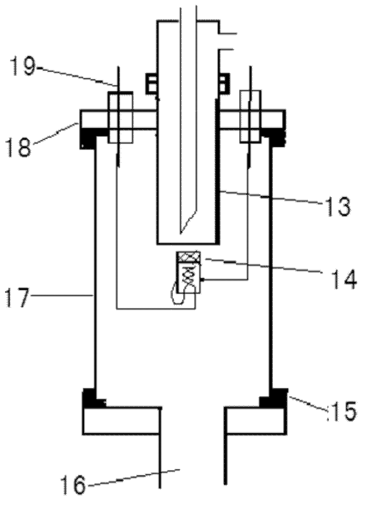
[0029] image 3 It is a structural schematic diagram of a specific embodiment of the cathode emission testing device of the present invention. Such as image 3 As shown, reference numeral 13 is an anode, 14 is a cathode, 15 is a sealing ring, 16 is an exhaust flange, 17 is a tube she...


PUM


Abstract

The invention discloses a cathode emission testing apparatus and system for microwave vacuum electronic devices. In the apparatus, an anode and an electrode are mounted on the same flange; a cathode is connected to the electrode; the flange is fixed at an end of a tube; and both ends of the tube are sealed with seal rings. The apparatus and the system in the invention have the advantages of being simple and easy to implement and being capable of very easily and conveniently controlling the distance and depth of parallelism between the anode and the cathode.

Description

technical field [0001] The invention belongs to the technical field of microwave vacuum electronic devices, in particular to a cathode emission testing device and system for microwave vacuum electronic devices, which are used for cathode emission testing of microwave vacuum electronic devices. Background technique [0002] Microwave vacuum electronic devices are widely used in radar, satellite communications, electron accelerators, global positioning, controllable thermonuclear fusion and high-power microwave weapons at the frontier of the military in the future. In the case of high frequency band, it cannot be replaced by other devices. After decades of development, although the theory of conventional microwave vacuum electronic devices and related technologies has been basically mature, modern high-tech microwave devices have continuously put forward new development requirements for the power, frequency, bandwidth and other working characteristics of microwave signals. The...

Claims


Application Information

Patent Timeline
Patent Type & Authority Applications(China)
IPC IPC(8): G01R31/25H01J9/42
Inventor 刘燕文朱虹李玉涛田宏孟鸣凤邯娇邓峰刘濮鲲
Owner INST OF ELECTRONICS CHINESE ACAD OF SCI
Why Eureka
Try Eureka