A light source shaping method and structure for projection

A technology of light source and laser light source, which is applied in the field of optoelectronics, can solve the problems that the design requirements are difficult to meet the precision requirements, reduce the optical quality of the beam, and reduce the beam interval.

Active Publication Date: 2016-04-06
HISENSE
View PDF7 Cites 0 Cited by
  • Summary
  • Abstract
  • Description
  • Claims
  • Application Information

AI Technical Summary

Problems solved by technology

As mentioned above, the single-array lasers are used to deflect and combine the beams as a whole. It is also possible to use reflectors to cooperate with multi-array lasers to achieve beam shaping to a certain array of laser beams. For example, two sets of laser arrays are vertically placed. Intersect with another group of parallel beams to form a beam, but these processing methods have a limited reduction in the interval between beams. Due to the influence of the mirror arrangement, the spot size cannot be further compressed, that is, the spot size cannot be flexibly controlled according to needs.
[0006] In addition, whether it is a single-array or multi-array laser, when using reflectors for beam shaping, each laser beam is equipped with an independent reflector to achieve beam shaping, or each group of lasers in the laser array is configured with an independent reflector to achieve beam shaping. This kind of configuration structure, in the process of deflecting the laser beam transmission direction, it is impossible to fully meet the design requirements or it is difficult to meet the complete accuracy requirements, so the spot after shaping is composed of many small beams with slight deviations in multiple transmission directions , but not completely in the same direction, which greatly reduces the optical quality of the combined beam
Due to the widespread use of the above-mentioned existing structures, optimization measures such as improving mechanical precision are generally adopted to reduce deviations. So far, there is no data showing that there is a design that breaks through this structure, especially the structure of the improved mirror unit.

Method used


Image

  • A light source shaping method and structure for projection
  • A light source shaping method and structure for projection
  • A light source shaping method and structure for projection

Examples


Embodiment Construction

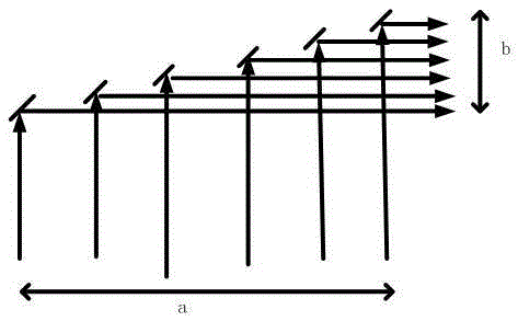
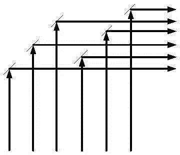
[0028] According to the arrangement of the laser array, the present invention divides the laser array into several large parts, each part is reflected by a group of mirrors placed on the same plane, and the mirrors of the same group are assembled on the same plane, but there are gaps between the mirrors. void. For example, every five columns of light beams form a group, and the reflectors of this group can be arranged on a large planar structure as follows. There is also a space between each reflector.

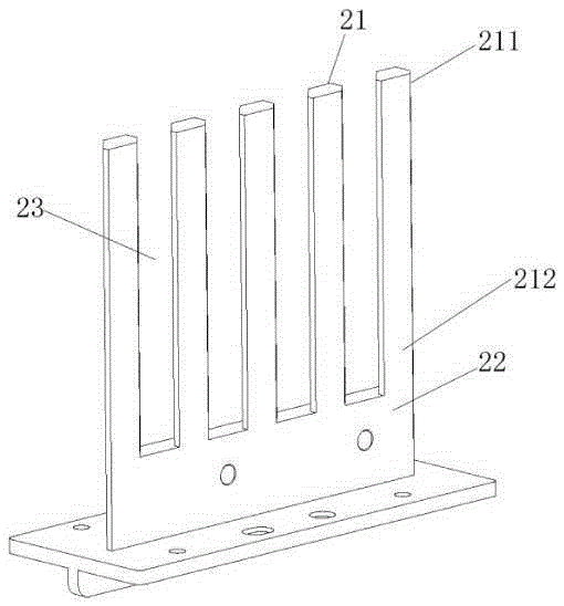
[0029] Such as figure 2 As shown, the reflector group is composed of five reflectors 21 and their fixing parts 22 , each set of reflectors has a predetermined interval between each reflector, and each reflector can be used to reflect multiple light beams. When part of the laser beams of the laser array are irregularly spaced or inconsistent with other parts, the space between the mirrors, that is, the gap 23 can be the same or can be set to different widths according to the a...


PUM


Abstract

Certain aspects of the disclosure relates to a light beam shaping apparatus, which includes at least one reflector unit disposed on a light beam transmission optical path. Each of the at least one reflector unit includes at least two reflectors. Each of the at least two reflectors includes a reflector body; a reflecting surface disposed on the reflector body; and a fixing portion supporting the reflector body. The reflecting surfaces of the at least two reflectors are disposed on a same plane.

Description

technical field [0001] The invention relates to the field of optoelectronics, in particular to a light source shaping structure, method and laser display device. Background technique [0002] At present, projection display products are developing rapidly, and the brightness is constantly improving. Most of the light sources used in projection products are LEDs of three primary colors. Due to the poor spatial beam quality of the LED output light and the large optical expansion, it is difficult to achieve light output. Therefore, the laser excitation phosphor solution came into being. The laser power usually used for excitation is above tens of watts, which is realized by a low-power blue laser array. [0003] The mainstream laser light source projectors generally use a laser beam to excite a phosphor wheel to generate the required display light source. When the brightness is high, the required laser power may be as high as tens of watts, or even more than 100 watts. . Suc...

Claims


Application Information

Patent Timeline
Patent Type & Authority Patents(China)
IPC IPC(8): G03B21/28G02B27/09
CPCG02B27/0977
Inventor 田有良
Owner HISENSE
Why Eureka
Try Eureka