Reflection type objective lens structure and manufacturing method thereof
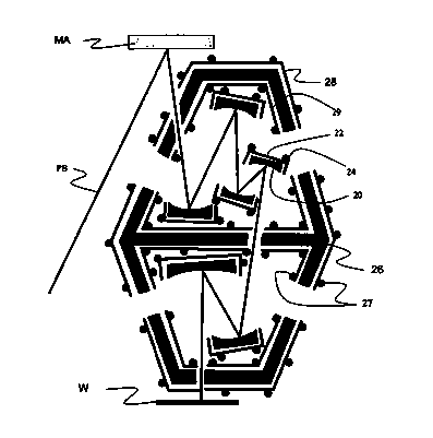
A technology supported by mirrors and mirrors, applied in the field of lithography, can solve the problems of large internal space of lithography machines, unfavorable dynamic performance of the whole machine, unfavorable exposure accuracy, etc., to ensure high-precision lithography resolution and simple structure of objective lens High efficiency and improved dynamic stability
- Summary
- Abstract
- Description
- Claims
- Application Information
AI Technical Summary
Problems solved by technology
Method used
Image
Examples
no. 1 approach
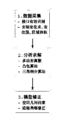
[0052] This implementation mode provides a kind of manufacturing method of polyhedron objective lens structure, and its flow process is as follows figure 2 As shown, it specifically includes the following steps:
[0053] Step S1: Data collection.
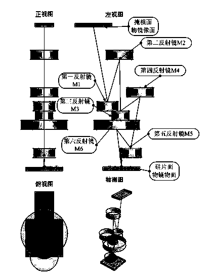
[0054] image 3 Shown is the required optical path of the polyhedral objective lens and the structure diagram when it is formed in the form of a mirror. First, the installation position of the polyhedral mirror in three-dimensional space and the layout of the optical path in space are determined according to the optical design. In addition, effectively identify and define the location of the installation area of the mirror support device, lens device, measurement system, adjustment device and cooling system device inside the polyhedron objective lens, and clarify the location points of all relevant interfaces or the three-dimensional space data of the installation area. In this embodiment, the objective lens specifically includ...
no. 2 approach
[0063] This embodiment provides a method for manufacturing a polyhedral objective lens structure, the process of which is the same as that of the first embodiment, including:
[0064] Step S1: Data collection.
[0065] image 3 Shown is the required optical path of the polyhedral objective lens and the structure diagram when it is formed in the form of a mirror. First, the installation position of the polyhedral mirror in three-dimensional space and the layout of the optical path in space are determined according to the optical design. In addition, effectively identify and define the location of the installation area of the mirror support device, lens device, measurement system, adjustment device and cooling system device inside the polyhedron objective lens, and clarify the location points of all relevant interfaces or the three-dimensional space data of the installation area. In this embodiment, the objective lens specifically includes all mirrors, all mirror support devi...
no. 3 approach
[0073] This embodiment provides a method for manufacturing a polyhedral objective lens structure, the process of which is the same as that of the first embodiment, including:
[0074] Step S1: Data collection.
[0075] image 3 Shown is the required optical path of the polyhedral objective lens and the structure diagram when it is formed in the form of a mirror. First, the installation position of the polyhedral mirror in three-dimensional space and the layout of the optical path in space are determined according to the optical design. In addition, effectively identify and define the location of the installation area of the mirror support device, lens device, measurement system, adjustment device and cooling system device inside the polyhedron objective lens, and clarify the location points of all relevant interfaces or the three-dimensional space data of the installation area. In this embodiment, the objective lens specifically includes all mirrors, all mirror support devi...
PUM
 Abstract
Description
Claims
Application Information
 - R&D Engineer
- R&D Manager
- IP Professional
- Industry Leading Data Capabilities
- Powerful AI technology
- Patent DNA Extraction
Browse by: Latest US Patents, China's latest patents, Technical Efficacy Thesaurus, Application Domain, Technology Topic, Popular Technical Reports.
© 2024 PatSnap. All rights reserved.Legal|Privacy policy|Modern Slavery Act Transparency Statement|Sitemap|About US| Contact US: help@patsnap.com


