Powder box for electrophototgraphic imaging device and method for resetting detection gear thereof

An imaging device and an electrophotographic technology, which are applied to an electrical recording process using a charge pattern, equipment for an electrical recording process applying a charge pattern, and an electrical recording technique, can solve the problem of high requirements on reset switch sensitivity, and powder cartridge reset detection. The gear is troublesome, and it is impossible to accurately detect whether the powder box is installed in place, etc., so as to solve the problem of troublesome and easy reset of the detection gear.

Active Publication Date: 2014-03-26
ZHUHAI NINESTAR INFORMATION TECH CO LTD
View PDF5 Cites 2 Cited by
  • Summary
  • Abstract
  • Description
  • Claims
  • Application Information

AI Technical Summary

Problems solved by technology

[0008] The invention provides a powder box for an electrophotographic imaging device to solve the trouble of resetting the detection gear of the powder box for the existing electrophotographic imaging device, and the existing powder box for the electrophotographic imaging device cannot accurately detect the powder box after the reset switch is reset Whether it is installed in place and the technical issues that require high sensitivity of the reset switch

Method used


Image

  • Powder box for electrophototgraphic imaging device and method for resetting detection gear thereof
  • Powder box for electrophototgraphic imaging device and method for resetting detection gear thereof
  • Powder box for electrophototgraphic imaging device and method for resetting detection gear thereof

Examples


Embodiment 1

[0046]The powder box A used in the present invention includes a developing element, a powder feeding element, a stirring element and carbon powder; Feed the powder-feeding element, the powder-feeding element is in contact with the developing element during the working process, and transports the carbon powder to the developing element, so that the charged carbon powder is attached to the developing element.

[0047] Such as figure 1 Shown is the three-dimensional schematic diagram of powder box A adopted in the present invention, figure 2 Shown is a schematic diagram of the front of the powder box A after removing the protective cover; figure 1 , 2 As shown, the powder box A also includes a powder box main body 1, a driving gear set 2, a detection gear 3 and a protective cover 5; toner is contained in the powder box main body 1; the driving gear set 2 and the detection gear 3 are arranged on the powder box main body 1 The protective cover 5 is assembled on the outside of t...

Embodiment 2

[0063] In this embodiment, the same structure or working process as in Embodiment 1 will not be described again here.

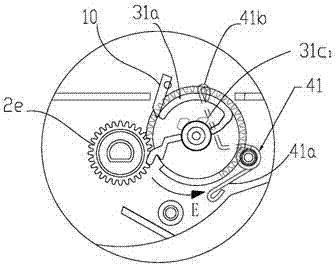
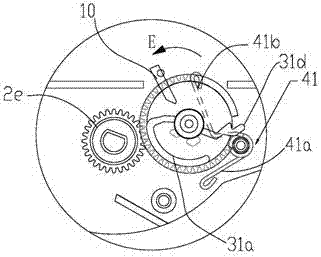
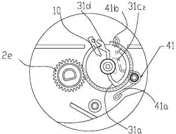
[0064] The difference from Example 1 is that, if Figure 7a As shown, the upper gear of the stirring element gear 22e is only partially provided with teeth on the circumference, and the upper gear meshes with the detection gear 3; Figure 7b As shown, the powder box is in the initial state (the state during production); when the stirring element gear 22e is in the state shown in the figure, the upper gear of the stirring element gear 22e is not meshed with the gear part on the detection gear 3, and the stirring element gear 22e is receiving After being rotated by the driving force from the electrophotographic imaging device, the upper gear meshes with the detection gear 3 and drives the detection gear 3 to rotate, so the detection gear 3 does not rotate synchronously with the driving gear set 2 during the working process of the powder box. Because the reset ...

Embodiment 3

[0067]In this embodiment, the same structure or working process as in Embodiment 2 will not be described again here.

[0068] Figure 8a Shown is a three-dimensional schematic diagram of the detection gear 33 used in this embodiment; the detection gear 33 is provided with a protruding part 33a, a notch 33b and an installation detection part 33d; the protruding part 33a and the installation detection part 33d are arranged on the same cylinder, and the outer surface The surface is in contact with the reset switch 10 during the operation of the powder container, so that the powder container A can be detected by the electrophotographic imaging device; the notch 33b on the protruding part 33a is provided on the cylindrical surface of the protruding part 33a.

[0069] When an unused powder container is installed on the electrophotographic imaging device, the detection gear 33 is in Figure 8b In the state shown, the protruding part 33a is in contact with the reset switch 10 so that...


PUM


Abstract

The invention relates to a powder box for an electrophototgraphic imaging device, which comprises a powder box main body, a driving gear set and a detection gear, wherein the detection gear comprises a projecting part and a gear part; the gear part is only arranged on part of the circumferential upper part of the detection gear; the gear part meshes with one gear in the driving gear set; the electrophototgraphic imaging device is provided with a resetting switch; under the driving action of the driving gear set and the gear part, the projecting part contacts or does not contact the resetting switch on the electrophototgraphic imaging device; the projecting part is arranged on a cylindrical post; and the cylindrical post is provided with a notch. The contact or separation time of the projecting part and resetting switch is prolonged, thereby lowering the requirements for the sensitivity of the resetting switch.

Description

technical field [0001] The invention relates to an electrophotographic imaging device (such as a laser printer, copier, facsimile machine, etc.), in particular to a powder box for an electrophotographic imaging device and a method for resetting a detection gear thereof. Background technique [0002] In the prior art, an electrophotographic imaging device, such as a laser printer, adopts a technology for identifying whether the powder box is used for the first time. This technology activates the reset switch on the printer through the detection mechanism on the powder box, so that the printer The storage unit that stores the printing information on the printer is reset so that the CPU on the printer can calculate the service life of the printer. This technology is disclosed in US Patent Publication No. US5,430,780. In this patent, the gear element (F1) and its protruding part (F1b ) is the above-mentioned detection mechanism. [0003] In this technology, before the toner car...

Claims


Application Information

Patent Timeline
Patent Type & Authority Applications(China)
IPC IPC(8): G03G15/00G03G15/08
Inventor 黄万红王鹏杨浩吴连俊刘金莲
Owner ZHUHAI NINESTAR INFORMATION TECH CO LTD
Why Eureka
Try Eureka