Eureka AIR delivers breakthrough ideas for toughest innovation challenges, trusted by R&D personnel around the world.

Touch control panel and touch control display panel

A touch panel and touch sensing layer technology, which is applied in the fields of instruments, electrical digital data processing, and data processing input/output processes, etc. Problems such as peeling occur to achieve the effect of good yield

Inactive Publication Date: 2014-03-26
AU OPTRONICS CORP
View PDF5 Cites 15 Cited by
  • Summary
  • Abstract
  • Description
  • Claims
  • Application Information

AI Technical Summary

Problems solved by technology

[0004] However, due to the problem of poor adhesion between the sensing electrode and the sensing line (trace line), the protective film temporarily used in the post-stage tearing process (such as removing the peelable adhesive or removing the process) and other processes), the film layer at the junction is prone to peeling (peeling)
As a result, the yield rate of the touch panel is reduced

Method used


Image

  • Touch control panel and touch control display panel
  • Touch control panel and touch control display panel
  • Touch control panel and touch control display panel

Examples


Embodiment Construction

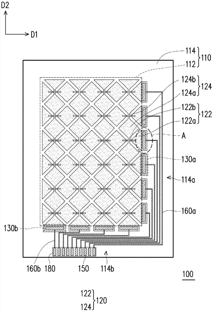
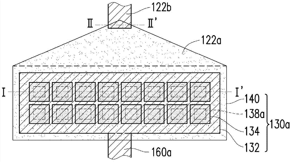
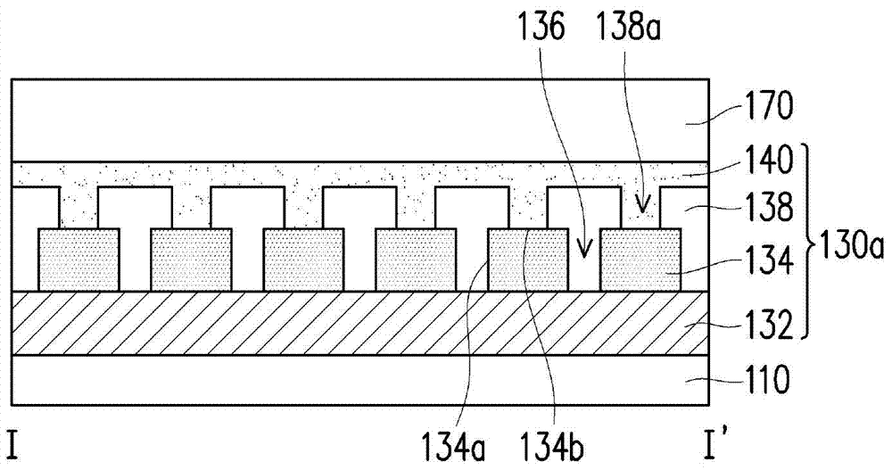
[0067] Figure 1A is a schematic top view of a touch panel according to an embodiment of the present invention, Figure 1B for Figure 1A An enlarged schematic view of region A of , and Figure 1C and Figure 1D respectively along Figure 1B The cross-sectional schematic diagram of line I-I' and line II-II'. Please also refer to Figure 1A to Figure 1DThe touch panel 100 includes a substrate 110 , a touch sensing layer 120 , transfer structures 130 a , 130 b , contact pads 150 , and connecting wires 160 a , 160 b. The substrate 110 has a sensing area 112 and a peripheral area 114 . In this embodiment, the substrate 110 is a transparent substrate, such as a glass substrate, a plastic substrate, a flexible substrate or other substrates. The peripheral area 114 is, for example, surrounding the sensing area 112 , and the peripheral area 114 is, for example, overlapping with the black matrix pre-shading area. That is to say, in the touch panel 100 , the sensing area 112 is, f...


PUM


Abstract

A touch control panel comprises a substrate and a touch control sensing layer located in a sensing region and further comprises an adapter structure, a contact pad and a connecting wire in the peripheral region. The adapter structure is electrically connected with the touch control sensing layer and comprises a conductor electrode, a plurality of transparent conductor island patterns, an insulating layer and a transparent conductor layer. The transparent conductor island patterns are arranged on the conductor electrode. A plurality of gaps of the conductor electrode are exposed between the transparent conductor island patterns. The insulating layer covers the transparent conductor island patterns and is provided with a plurality of openings. The insulating layer is disposed in the gaps and contacted with the conductor electrode and covers the side edges and partial top surfaces of the transparent conductor island patterns, the openings exposing the transparent conductor island patterns. The transparent conductor layer is arranged on the insulating layer and is electrically connected with the transparent conductor island patterns through the openings. The connecting wire is connected with the adapter structure and the contact pad.

Description

technical field [0001] The present invention relates to a panel, and in particular to a touch panel and a touch display panel. Background technique [0002] Touch panels are roughly classified into resistive touch panels, capacitive touch panels, optical touch panels, acoustic wave touch panels, and electromagnetic touch panels according to their sensing methods. Among them, the capacitive touch panel (Capacitive Touch Panel) has attracted attention due to the rapid growth of sales of smart phones. [0003] In general, a touch panel includes a sensing area and a peripheral area. The sensing area includes sensing electrodes respectively extending in the X and Y directions for locating the touch position of an object, and the peripheral area includes sensing lines. (traceline), used to transmit the driving signal of the circuit board to the sensing electrode, and the sensing signal sensed by the sensing electrode is transmitted to the back-end circuit for calculation of the t...

Claims


Application Information

Patent Timeline
Patent Type & Authority Applications(China)
IPC IPC(8): G06F3/041
Inventor 吴佩蓉陈建宇
Owner AU OPTRONICS CORP
Why Eureka
Eureka Blog
Learn More