Multi-pole magnetic ring magnetizing equipment with full-automatic feeding, discharging and magnetizing functions

A technology of multi-pole magnetic rings and magnetizing equipment, which is applied in the direction of conveyors, magnetic objects, conveyor objects, etc., can solve the problems of large labor costs, low magnetization efficiency, and insufficient automation of enterprises, so as to reduce labor costs and improve The effect of magnetizing efficiency and easy installation

Inactive Publication Date: 2014-03-26
江门协立磁业高科技有限公司
View PDF6 Cites 14 Cited by
  • Summary
  • Abstract
  • Description
  • Claims
  • Application Information

AI Technical Summary

Problems solved by technology

[0002] The means or methods of magnetizing magnetic products are realized by using different magnetizing equipment according to the performance requirements of magnetic products or different use occasions. The magnetic ring plays an important role in ensuring the normal operation of electronic equipment. The common magnetic ring magnetization in the market The equipment requires workers to sort out the magnetic pieces continuously and then send them to the magnetizing equipment for magnetization. During magnetization, the magnetization head is manually driven. When the magnetization is completed, the workers need to take out the magnetic ring by hand, and then cycle the material. , magnetization, and blanking actions, this kind of magnetization equipment requires workers to operate continuously, is not automatic enough, the magnetization efficiency is low, wastes labor, and easily brings large labor costs to enterprises

Method used


Image

  • Multi-pole magnetic ring magnetizing equipment with full-automatic feeding, discharging and magnetizing functions
  • Multi-pole magnetic ring magnetizing equipment with full-automatic feeding, discharging and magnetizing functions
  • Multi-pole magnetic ring magnetizing equipment with full-automatic feeding, discharging and magnetizing functions

Examples


Embodiment Construction

[0019] The present invention will be described in further detail below in conjunction with the accompanying drawings and embodiments.

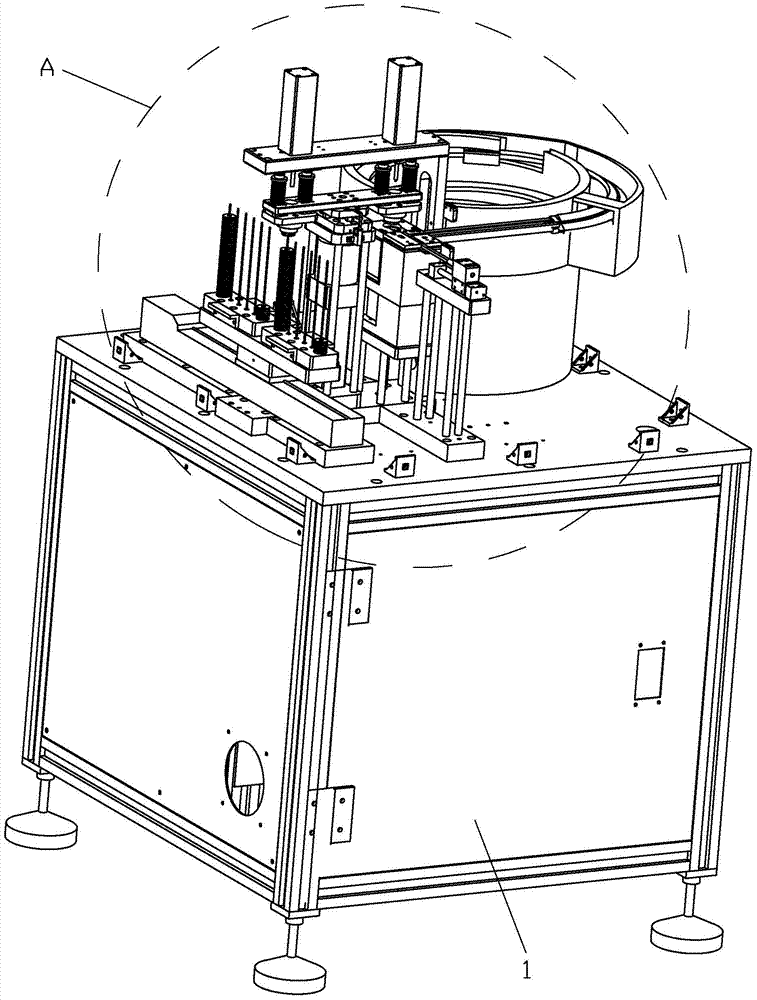
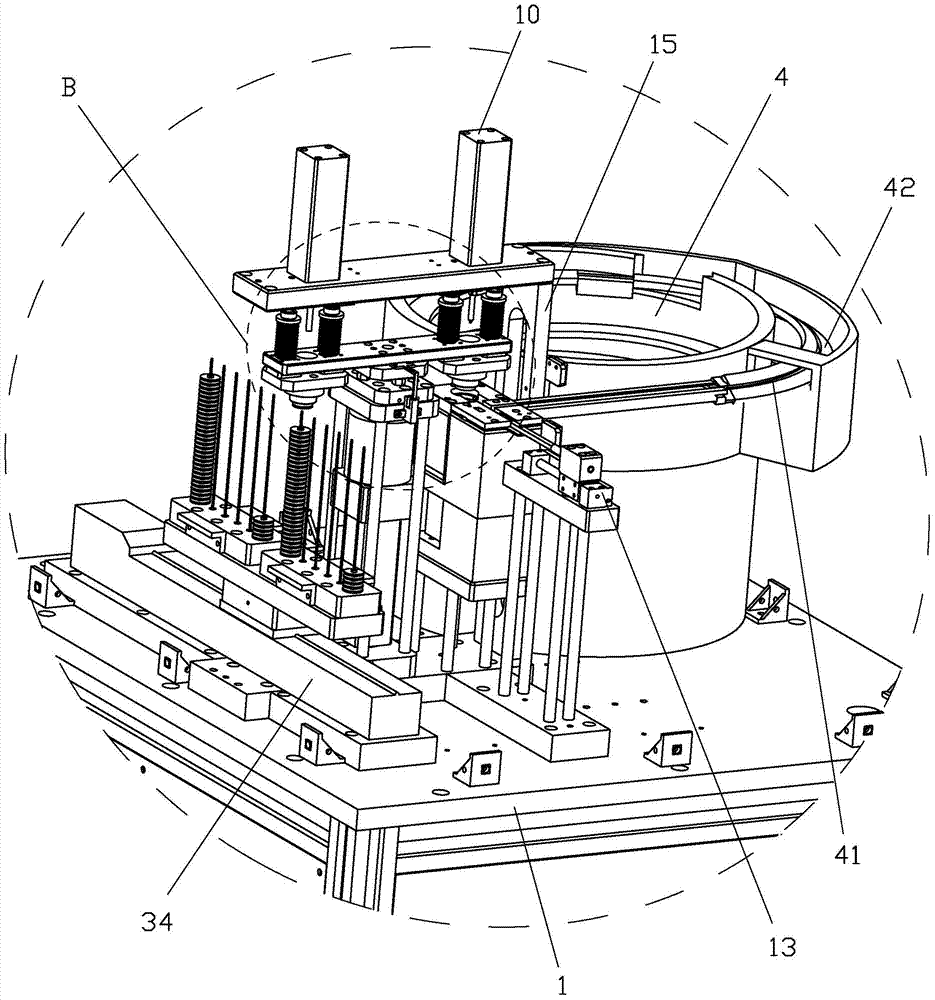
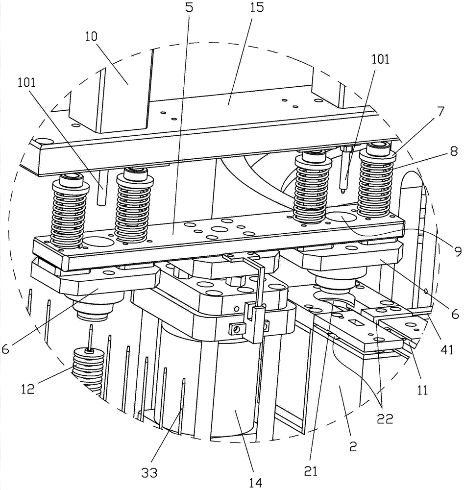
[0020] refer to Figure 1~Figure 4 , a kind of feeding, blanking and magnetizing automatic multi-pole magnetic ring magnetization equipment of the present invention comprises a base 1, a magnetization base 2 and a material receiving table 3 are arranged on the base 1, and the magnetization base 2 is A magnetizing hole 21 for accommodating the magnetic ring 12 and magnetizing the magnetic ring 12 is provided. The base 1 is also provided with a vibrating feeder 4, and the vibrating feeder 4 is provided with a spiral feeding groove rail 41. The vibrating feeder 4 with the spiral feeding groove rail 41 is a known technology in the feeding field, and its specific structure will not be described in detail here; Through the docking of the groove 22, the magnetic ring 12 on the feeding groove rail 41 pushes each other, so that the magnetic ring 12 at...


PUM


Abstract

The invention discloses a set of multi-pole magnetic ring magnetizing equipment with the full-automatic feeding, discharging and magnetizing functions. A magnetic ring can be automatically fed through a vibrating feeding machine, through the arrangement of a rotating plate and a pushing oil cylinder, when a magnetizing head is made to be located above a magnetizing hole, after a push rod of the pushing oil cylinder acts to penetrate through a through hole in the rotating plate, the magnetizing head is pushed to fall into the magnetizing hole, the magnetic ring in the magnetizing hole can be magnetized automatically, meanwhile, after the push rod of the pushing oil cylinder located above a material collecting table acts to penetrate through the through hole of the rotating plate and a through hole in the magnetizing head, the magnetic ring attracted to the bottom end of the magnetizing head is pushed away from the magnetizing head, and thus automatic discharging is achieved. The manual feeding, magnetizing and discharging method in the traditional technology is abandoned, full-automatic feeding, magnetizing and discharging of the magnetizing equipment are achieved, the magnetizing efficiency is greatly improved, and labor cost is reduced. The multi-pole magnetic ring magnetizing equipment is simple, reasonable and compact in structure, convenient to install and easy to implement and can meet industry development requirements better.

Description

technical field [0001] The invention relates to a magnetizing device for a multi-pole magnetic ring. Background technique [0002] The means or methods of magnetizing magnetic products are realized by using different magnetizing equipment according to the performance requirements of magnetic products or different use occasions. The magnetic ring plays an important role in ensuring the normal operation of electronic equipment. The common magnetic ring magnetization in the market The equipment requires workers to sort out the magnetic pieces continuously and then send them to the magnetizing equipment for magnetization. During magnetization, the magnetization head is manually driven. When the magnetization is completed, the workers need to take out the magnetic ring by hand, and then cycle the material. , Magnetization, and blanking actions, this kind of magnetization equipment requires workers to operate continuously, is not automatic enough, has low magnetization efficiency,...

Claims


Application Information

Patent Timeline
Patent Type & Authority Applications(China)
IPC IPC(8): H01F13/00B65G27/02B65G47/82
Inventor 林国盛林炳炎朱炳财
Owner 江门协立磁业高科技有限公司
Why Eureka
Try Eureka