Power electronic device, power electronic system and hot plugging method of power unit

A technology for power electronic devices and power units, which is applied in the direction of boards/panels/desks, switch devices, electrical components, etc. and other problems, to achieve the effect of safe operation and easy maintenance

Active Publication Date: 2014-03-26
DELTA ELECTRONICS INC
View PDF3 Cites 4 Cited by
  • Summary
  • Abstract
  • Description
  • Claims
  • Application Information

AI Technical Summary

Problems solved by technology

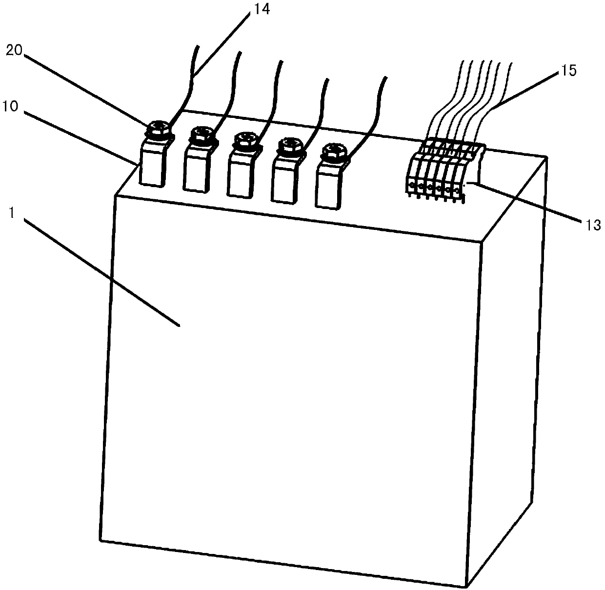
Since the power line 14 and the signal line 15 are directly connected to the power unit 1, the movement range of the power unit 1 is limited, resulting in that the power electronic device cannot be freely plugged and unplugged relative to the cabinet.
If a certain power electronic device in the power electronic system fails, the entire power electronic system can only be shut down for repair or replacement, which seriously affects the working efficiency of the power electronic system
[0004] Therefore, in the traditional power electronic system, it is impossible to realize the free plug function of the power electronic device relative to the cabinet, and it is impossible to repair or replace one of the faulty power electronic devices when other power electronic devices are charged and working normally. The electronic device cannot realize the hot swap function

Method used


Image

  • Power electronic device, power electronic system and hot plugging method of power unit
  • Power electronic device, power electronic system and hot plugging method of power unit
  • Power electronic device, power electronic system and hot plugging method of power unit

Examples


Embodiment Construction

[0079] The aforementioned and other technical contents, features and effects of the present invention will be clearly presented in the following detailed description of preferred embodiments with reference to the accompanying drawings.

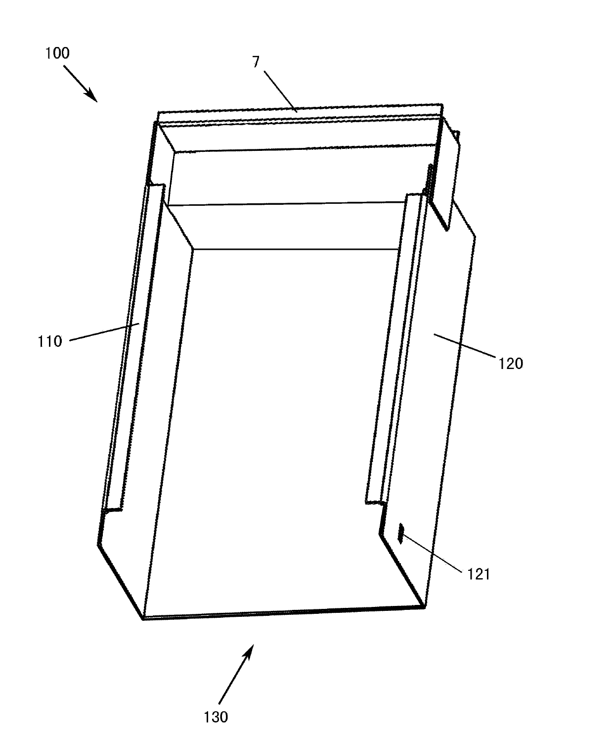
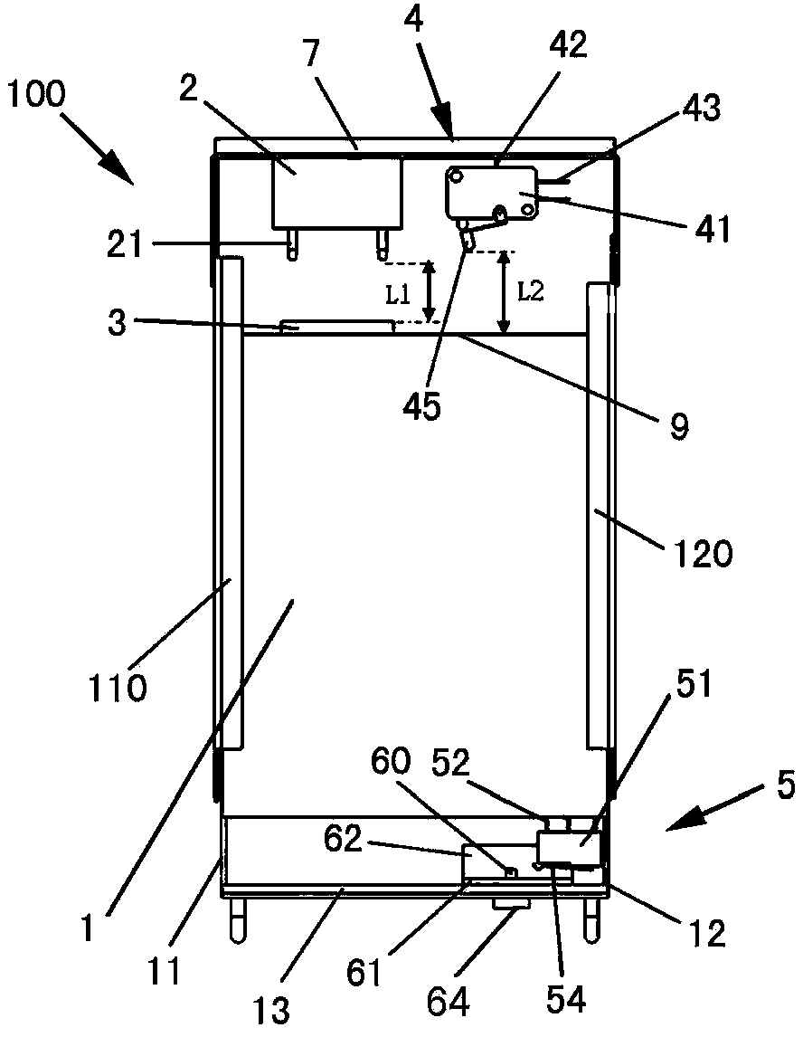
[0080] The technical idea of ​​the present invention is: take the power electronic device as the basic core, cooperate with the power supply, control output terminal and signal output terminal fixed on the installation grid, the power supply and control input terminal and signal input terminal fixed on the power unit, and the power supply unit Slide rails. The power unit slides on the guide rail to connect or disconnect the external current with the power unit, realizing the hot swap function of the power electronic device.

[0081] Power Electronics

[0082] see Figure 2A to Figure 7B . The power electronic device introduced here includes an installation grid 100 , and a power unit 1 and a micro switch 5 that are hot-swappable to the inst...


PUM


Abstract

The invention provides a power electronic device, a power electronic system and a hot plugging method of a power unit. The power electronic device includes a power unit and a mounting cell matched with the power unit; the mounting cell is provided with a guide rail and an entering/exiting opening; the power unit can be pushed in and pulled out through the guide rail and the entering/exiting opening; the mounting cell is further provided with a power supply, a control output end and a signal output end; the power unit is provided with a micro switch as well as a power supply, a control input end and a signal input end which are in matched connection with the above power supply, the control output end and the signal output end; when the power unit is accessed, the power unit is inserted into the mounting cell along the guide rail; the power supply and the control input of the power unit contact with the power supply and the control output end of the mounting cell such that the power supply and the control input of the power unit are in electric connection with the power supply and the control output end of the mounting cell; the signal input end of the power unit is in switch-on connection with the signal output end, and the micro switch is switched on, such that the power unit can be started. When the power unit is required to be pulled out, operation steps are opposite to the above steps. With the hot plug method of the power unit adopted, hot plugging or hot pulling out of the power unit with respect to the mounting cell can be realized under the situation that the whole power electronic system is electrified, and therefore, the work efficiency of the system can be improved greatly.

Description

technical field [0001] The invention relates to a power electronic device, a power electronic system and a hot plugging method for a power unit. Background technique [0002] In the traditional power electronic system, multiple IGBTs, inductors, capacitors, resistors and other components, which are the main components of the power part, are installed separately on the cabinet, and the power part has not been modularized. Only in individual power electronic systems, multiple IGBTs or multiple inductors, capacitors, resistors and other components are integrated into a power electronic device, that is, the power part is modularized. Usually a power electronic system will contain several power electronic devices. [0003] Such as figure 1 As shown, in the current power electronic system, each power electronic device includes a power unit 1 , a plurality of conductive terminals 10 , and a plurality of connection terminals 13 . The power line 14 connected to the power grid is c...

Claims


Application Information

Patent Timeline
Patent Type & Authority Applications(China)
IPC IPC(8): H02B1/04H02B1/052H02B1/20H02B3/00
CPCH05K5/0217H05K7/1432Y10T29/49117H05K7/14325H05K7/14339H05K5/0247
Inventor 严开田陈少华
Owner DELTA ELECTRONICS INC
Why Eureka
Try Eureka