Semi-automatic coil inserting machine

A wire-inserting, semi-automatic technology, applied in the manufacture of motor generators, electromechanical devices, electric components, etc., can solve the problems of difficulty in maintenance and debugging, high cost of paper inserting devices, unfavorable work efficiency, etc., and achieves convenient debugging and maintenance. Easy to change molds and small footprint

Inactive Publication Date: 2014-03-26
NIDE MECHANICAL EQUIP
View PDF7 Cites 3 Cited by
  • Summary
  • Abstract
  • Description
  • Claims
  • Application Information

AI Technical Summary

Problems solved by technology

The inlay of the stator is controlled by a mechanical device, and the slot cover paper or the slot cover bamboo is inserted at the same time. The insertion of the slot cover paper or the slot cover bamboo is mainly realized through the cooperation of the paper insertion device and the mold. The cost of the paper insertion device Very high, the failure rate is also high
Moreover, the thread embedding machine is generally equipped with a cam box for paper punching. This structure is very difficult in maintenance and debugging, and will also make the cost of the entire machine higher.
From the perspective of operation, the mold change of ordinary wire inserting machines is relatively complicated and difficult to operate, which is not conducive to improving work efficiency

Method used


Image

  • Semi-automatic coil inserting machine
  • Semi-automatic coil inserting machine
  • Semi-automatic coil inserting machine

Examples


Embodiment Construction

[0015] The preferred embodiments of the present invention will be described in detail below in conjunction with the accompanying drawings, so that the advantages and features of the present invention can be more easily understood by those skilled in the art, so as to define the protection scope of the present invention more clearly.

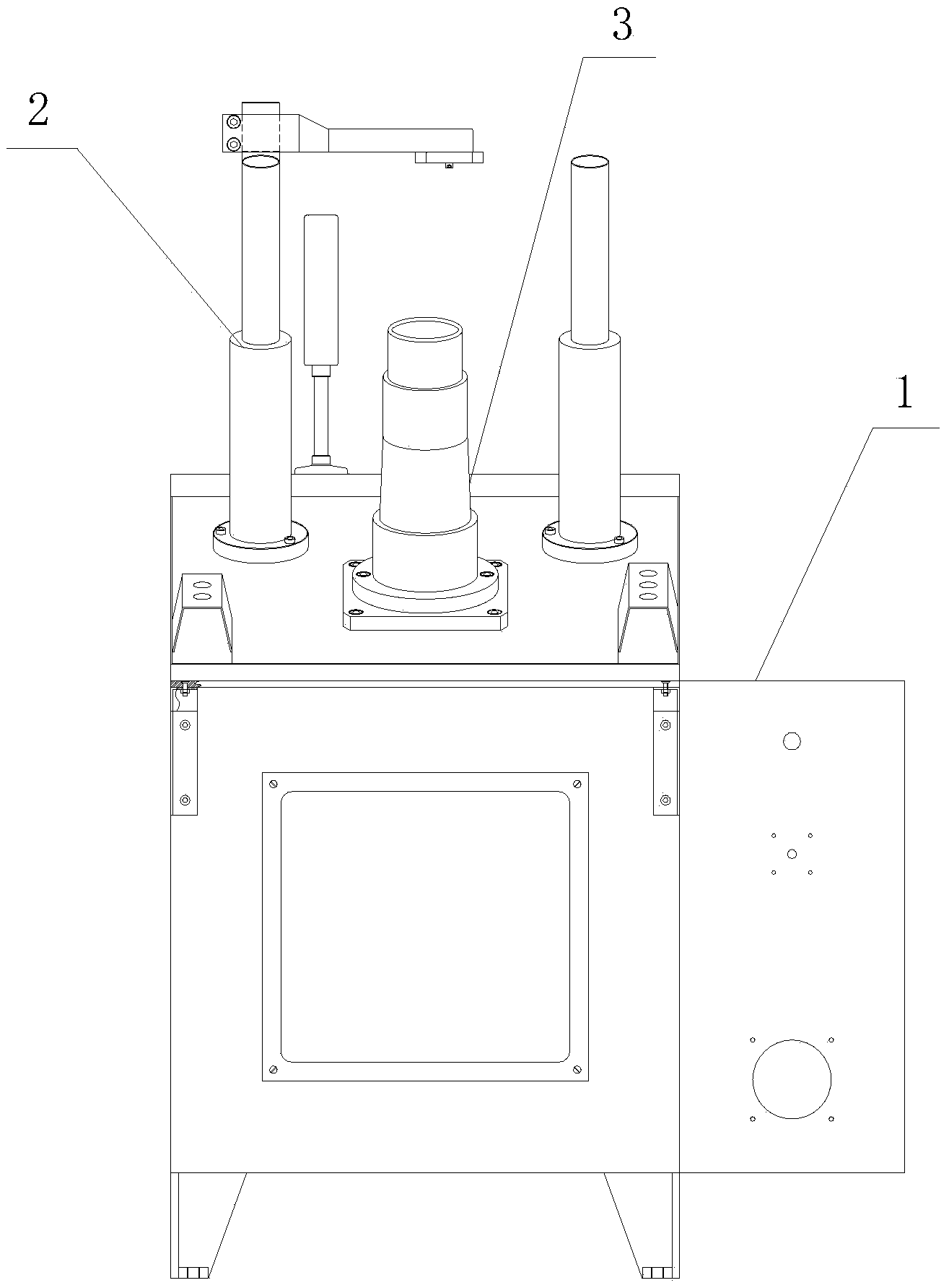
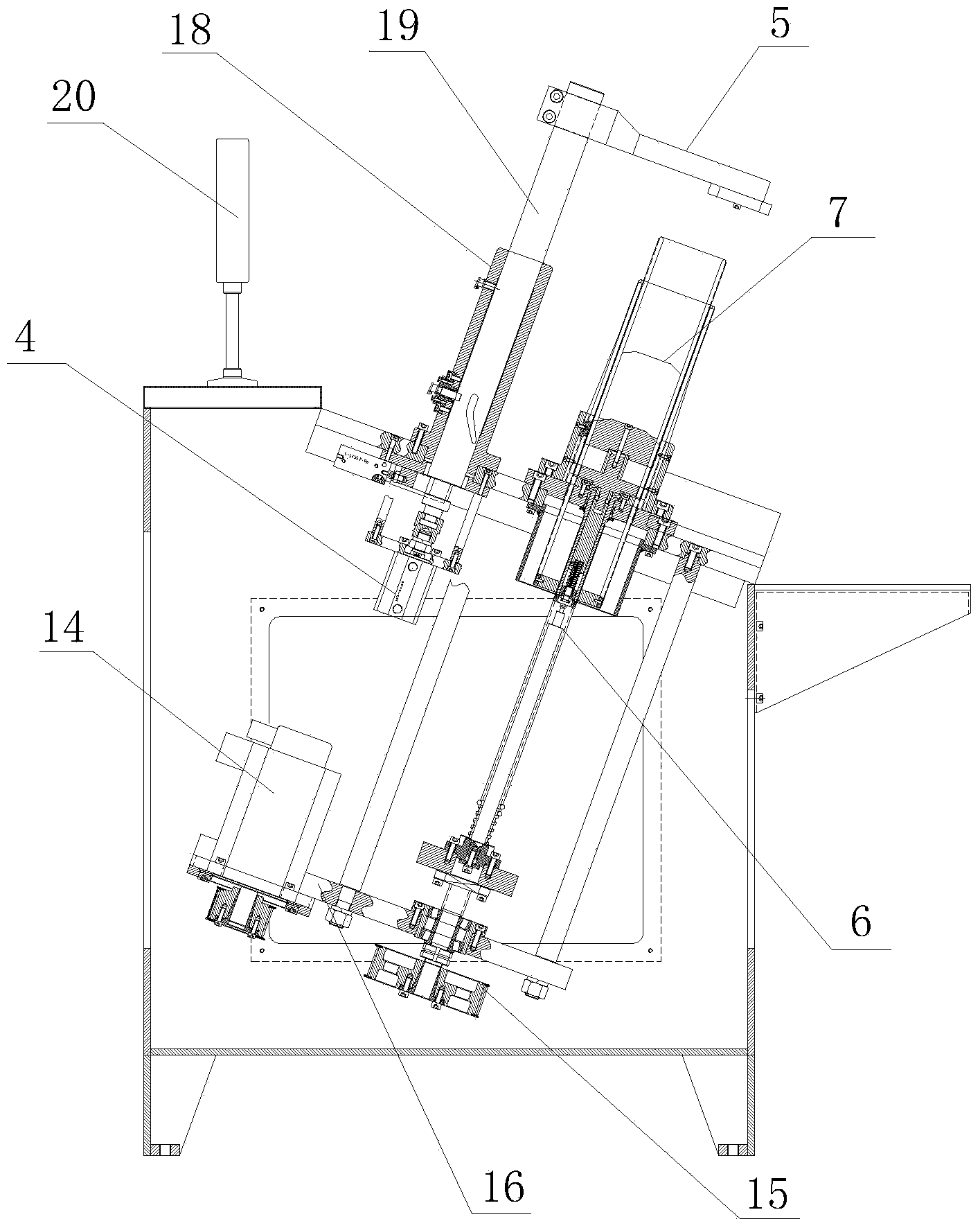
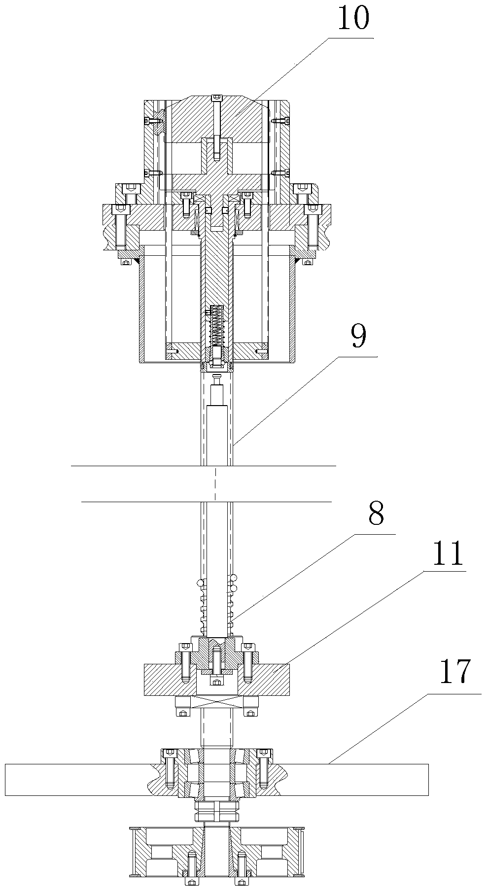
[0016] see Figure 1 to Figure 4 , the embodiment of the present invention includes:

[0017] A semi-automatic thread inserting machine, comprising a case 1 provided with a pressing arm mechanism 2 and a mold mechanism 3, and a warning light 20 is also provided on the case 1. Both the pressing arm mechanism 2 and the mold mechanism 3 are controlled by a PLC through a control system.

[0018] Wherein the pressing arm mechanism 2 comprises an oil cylinder 4, a guide sleeve 18 and a pressure rod 19, wherein the pressure rod 19 is slidably fitted in the guide sleeve 18, and the lower end of the pressure rod 19 is connected to the oil cylinder 4; the...


PUM


Abstract

The invention discloses a semi-automatic coil inserting machine comprising a case, a press arm mechanism, a mold mechanism and a control system. The press arm mechanism comprises a press block controlled by an oil cylinder. The mold mechanism comprises a push device and a mold device. The push device comprises a ball screw, a guide pillar and a copper push head. The ball screw, the guide pillar and the copper push head are connected with one another through a screw nut. The guide pillar and the screw nut are in sliding connection. The upper end of the ball screw is connected with the copper push head. The mold device comprises a storage strip and a guide strip. According to the semi-automatic coil inserting machine, improvements are made on the basis of an original coil inserting machine, and a cam box of a paper beating mechanism is omitted, so that occupation area of a machine body is small, production cost is reduced, and debugging and maintaining are greatly facilitated; the semi-automatic coil inserting machine is simple in structure, mold change is facilitated, mechanical working efficiency can be improved, and economic benefit can be increased.

Description

technical field [0001] The invention relates to the field of motor manufacturing equipment, in particular to a semi-automatic wire inserting machine. Background technique [0002] Inserting wire machine, also known as wire dropping machine, unloading machine, and wire feeding machine, is a mechanical production equipment in which the iron core of a motor is embedded in a coil. The inlay of the stator is controlled by a mechanical device, and the slot cover paper or the slot cover bamboo is inserted at the same time. The insertion of the slot cover paper or the slot cover bamboo is mainly realized through the cooperation of the paper insertion device and the mold. The cost of the paper insertion device Very high, and the failure rate is also high. Moreover, the thread embedding machine is generally provided with a cam box for beating paper. This structure is very difficult in maintenance and debugging, and also makes the cost of the whole machine higher. From the perspectiv...

Claims


Application Information

Patent Timeline
Patent Type & Authority Applications(China)
IPC IPC(8): H02K15/085
Inventor 熊庆华刘成章
Owner NIDE MECHANICAL EQUIP
Why Eureka
Try Eureka