Laser vision cooling device

A cooling device and laser technology, used in auxiliary devices, auxiliary welding equipment, welding/cutting auxiliary equipment, etc., can solve problems such as camera failure, camera collision, camera damage, etc., to achieve good monitoring effect, ensure normal operation, The effect of improving cooling efficiency

Inactive Publication Date: 2014-04-02
WENLING FENGYUN ROBOT
View PDF6 Cites 2 Cited by
  • Summary
  • Abstract
  • Description
  • Claims
  • Application Information

AI Technical Summary

Problems solved by technology

[0003] When laser vision technology is used for welding, the high heat generated by welding will affect the working temperature of the camera, causing the camera to not work normally; at the same time, the impurities generated by welding splash to the camera and collide with the camera. In severe cases, the camera will be damaged. Repair or replacement of the camera, resulting in prohibitive costs

Method used


Image

  • Laser vision cooling device
  • Laser vision cooling device
  • Laser vision cooling device

Examples


Embodiment Construction

[0024] The following are specific embodiments of the present invention and in conjunction with the accompanying drawings, the technical solutions of the present invention are further described, but the present invention is not limited to these embodiments.

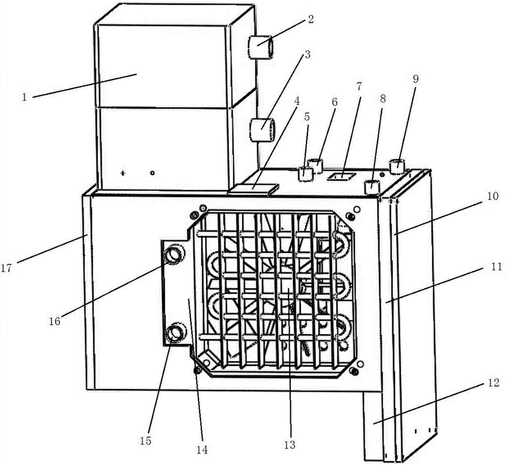
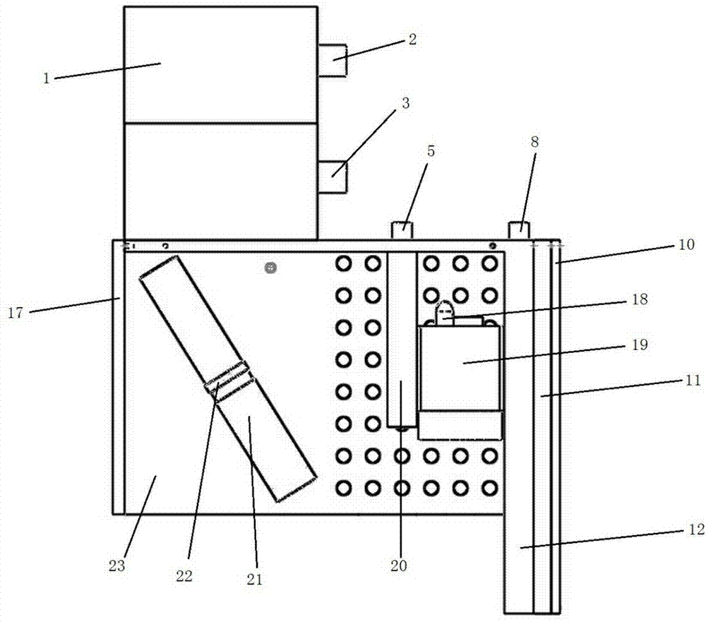
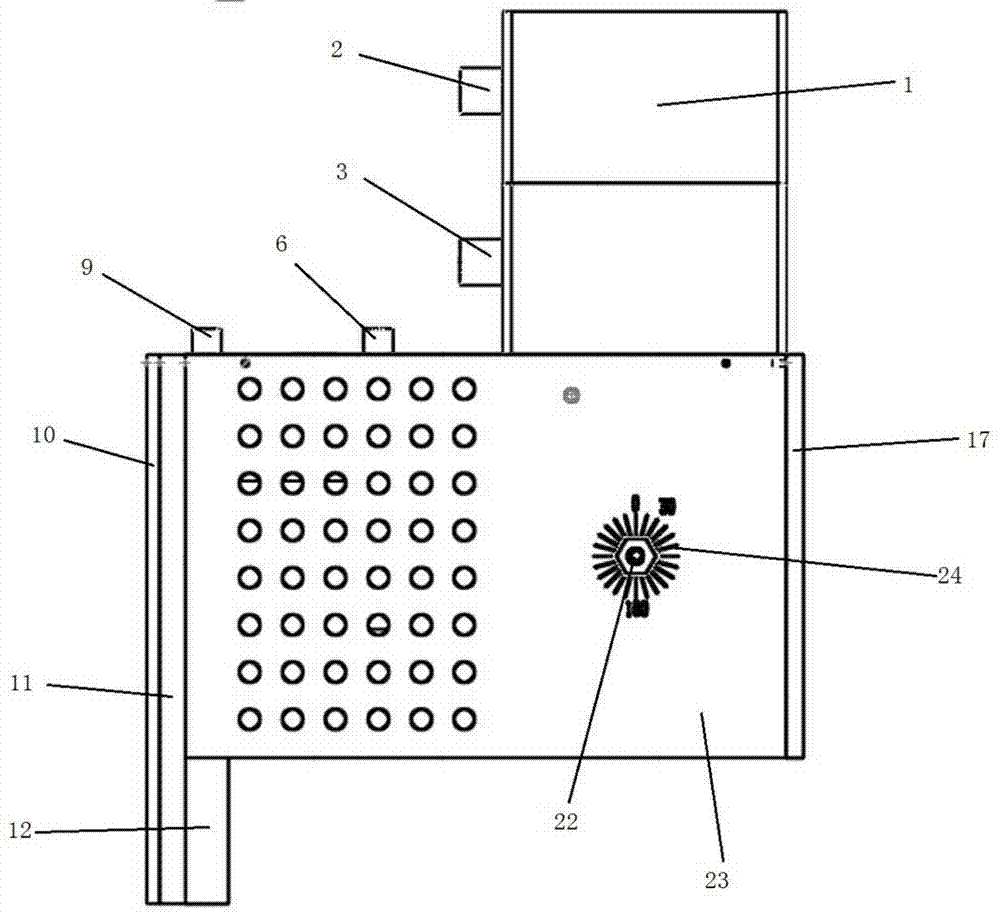
[0025] Such as figure 1 As shown, the laser vision cooling device includes a rectangular housing 23, a left baffle 17 located on the left side of the housing 23 and a right baffle 10 located on the right side of the housing 23, the left baffle 17 and the right baffle 10 play a fixed role. Such as figure 2 As shown, the housing 23 is also provided with a laser fixture 22 and a camera 19 , and the laser fixture 22 is provided with a laser 21 .

[0026] Such as figure 1 As shown, the top of the housing 23 is provided with a water pump 1 having a water inlet one 2 and a water outlet one 3 thereon, and the front part of the housing 23 is provided with a water cooling row 14 having a water inlet two 16 and a water outlet two...


PUM


Abstract

The invention provides a laser vision cooling device, belongs to the technical field of laser vision, and solves the problem that the existing laser vision system is poor in cooling effect. The laser vision cooling device comprises a rectangular shell, a left baffle and a right baffle, wherein the left baffle is arranged on the left side of the shell; the right baffle is arranged on the right side of the shell; a laser clamp and a camera are arranged in the shell; a laser is arranged on the laser clamp; a water pump with a water inlet I and a water outlet I is arranged on the top of the shell; a water cooling grate with a water inlet II and a water outlet II is arranged in the front of the shell; the water inlet II is communicated with the water outlet I; a metal plate I which is used for separating the laser from the camera and is internally provided with a cavity I is also arranged inside the shell; the metal plate I is attached to the camera and is provided with a water inlet III and a water outlet III which are respectively communicated with the cavity I; the water outlet II is communicated with the water inlet III; the water outlet III is communicated with the water inlet I. The laser vision cooling device has the advantages that the structure is compact, the cooling effect is good and the like.

Description

technical field [0001] The invention relates to a cooling device, in particular to a laser vision cooling device. Background technique [0002] Laser vision technology started in the 1980s. With the gradual maturity of this technology, many additional functions have been developed. At the same time, this technology is widely used, especially in the welded pipe industry. Laser vision systems generally use triangular structured light measurement to obtain three-dimensional information on the workpiece surface. Laser vision technology uses a laser as a structured light source. The laser is positioned at a specific angle to the camera, and the two are placed inside a compact sensor. When in use, the laser cylinder mirror projects the laser stripes onto the surface of the workpiece, and the camera captures the image of the laser stripes, and through triangulation matrix conversion, image processing and feature recognition, the three-dimensional information of the welding workpie...

Claims


Application Information

Patent Timeline
Patent Type & Authority Applications(China)
IPC IPC(8): B23K37/00
CPCB23K37/003
Inventor 叶渭忠张海波游于训沈鹏程
Owner WENLING FENGYUN ROBOT
Why Eureka
Try Eureka