Thermochromic smart window and preparation method thereof

A thermochromic and smart window technology, applied in chemical instruments and methods, layered products, metal layered products, etc., can solve the problem of high phase transition temperature of smart windows, and achieve the effect of broadening the scope of use

Inactive Publication Date: 2014-04-02
GLASS TECH RES INST OF SHAHE CITY OF HEBEI PROVINCE
View PDF4 Cites 9 Cited by
  • Summary
  • Abstract
  • Description
  • Claims
  • Application Information

AI Technical Summary

Problems solved by technology

[0003] The technical problem to be solved by the present invention is to provide a thermochromic smart window to solve the problem that the phase transition temperature of the current smart window is too high, so that the thermochromic window can be applied on a large scale

Method used


Image

  • Thermochromic smart window and preparation method thereof
  • Thermochromic smart window and preparation method thereof
  • Thermochromic smart window and preparation method thereof

Examples


Embodiment 1

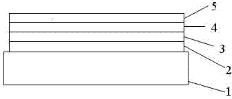
[0030] See attached figure 1 , the present embodiment is an all-thin-film structure, and its film layers from bottom to top are: substrate 1, electric heating layer 2, buffer layer 3, thermochromic layer 4, and protective layer 5. The preparation method of this embodiment is as follows:

[0031] See attached figure 1 ,

[0032] (1) Preparation of the substrate: cut a common flat glass substrate into a 10cm*10cm square, ultrasonically wash it in acetone for 10 minutes, and then ultrasonically wash it in alcohol for 20 minutes.

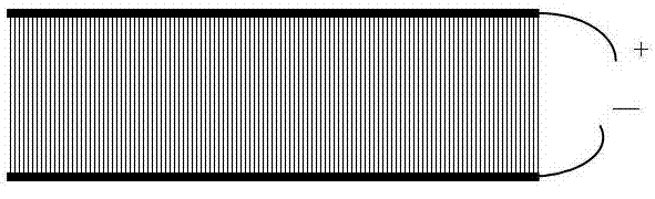
[0033] (2) Preparation of the electric heating layer: Prepare the electric heating layer on the cleaned substrate, print it with ITO transparent conductive glue, design a simple circuit diagram that can form a circuit on the screen in advance, bake it after printing, and put the prepared electric heating layer The substrate is fixed on the sample holder of the magnetron sputtering instrument. See attached image 3 or attached Figure 4 , horizonta...

Embodiment 2

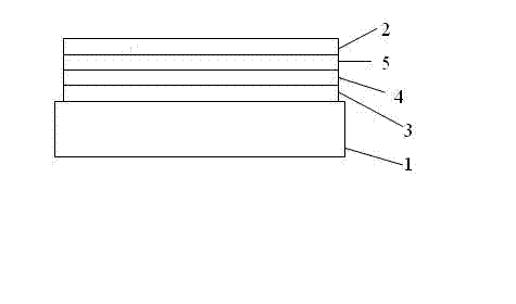
[0061] See attached figure 2 In this embodiment, the film layer structure from bottom to top is: substrate 1 , buffer layer 3 , thermochromic layer 4 , protective layer 5 , and electric heating layer 2 . The preparation method of this embodiment is as follows:

[0062] See attached figure 2 ,

[0063] (1) Preparation of the substrate: Cut a common flat glass substrate into a 10cm*10cm square, ultrasonically wash it in acetone for 10 minutes, and then ultrasonically wash it in alcohol for 20 minutes.

[0064] (2) Preparation of the buffer layer: use intermediate frequency or DC sputtering, select the target material Ti, and the reaction gas is Ar and O 2 , the substrate is heated to grow the buffer layer.

[0065] The specific parameters are as follows:

[0066] Substrate temperature: 500°C.

[0067] Gas ratio: Ar: O 2 =7:1;

[0068] Working pressure: 1.0Pa;

[0069] Sputtering power: 150W;

[0070] Sputtering time: 20min;

[0071] Film thickness: 80nm.

[0072] (...


PUM

PropertyMeasurementUnit
Thicknessaaaaaaaaaa
Film thicknessaaaaaaaaaa
Thicknessaaaaaaaaaa

Abstract

The invention discloses a thermochromic smart window and a preparation method thereof. The thermochromic smart window is of a full-film structure, and sequentially provided with a substrate, an electric heating layer, a buffer layer, a thermochromic layer and a protective layer, or a substrate, a buffer layer, a thermochromic layer, a protective layer and an electric heating layer from bottom to top, wherein the thermochromic layer material is VO2 doped with F<->, WOx or MgO. According to the preparation method, the thermochromic layer adopts medium-frequency or direct current sputtering; the thermochromic layer VO2 grows on the buffer layer; the target is V; 0.1-10% (wt%) of F<->, MgO, WOx or MoOx is introduced to the film layer in a doping manner; the gas adopts a mixed gas of Ar and O2; the volume ratio of Ar to O2 is 99:1 to 9:1.A composite structure of an electric heating material and a thermochromic material is adopted, and the temperature of the substrate is improved in an electric heating manner, so that the VO2 forcibly generates a phase change at room temperature, and the problems that the thermochromic film is relatively high in phase-transition temperature and cannot be practically applied are solved.

Description

technical field [0001] The invention belongs to the field of thermochromic smart windows, in particular to a composite structure smart window combined with an electric heating film and a thermochromic film. Background technique [0002] VO 2 The material is a phase-change material, which changes from a low-temperature semiconductor monoclinic phase to a metal tetragonal phase at a certain temperature. VO 2 After the phase change, the optical properties change, so that the infrared light transmittance decreases sharply and the reflectivity increases, which can effectively block the transmission of infrared rays and avoid the continuous rise of indoor temperature. When the temperature is lower than VO 2 The phase change temperature automatically restores the transmission of infrared light, so that the room temperature rises. Therefore, VO 2 The film is used in building windows, vehicle windows, etc., and can automatically adjust and control the room temperature according ...

Claims


Application Information

Patent Timeline
IPC IPC(8): B32B17/06B32B15/09B32B15/095B32B9/04B32B15/00B32B15/20B32B33/00
Inventor 栾晓波潘清涛陈支勇李娜程金树袁坚杨瑛
Owner GLASS TECH RES INST OF SHAHE CITY OF HEBEI PROVINCE
Why Eureka
Try Eureka