
Cyclone air flotation apparatus

A swirl air flotation and overflow technology, which is applied in the direction of flotation water/sewage treatment, etc., can solve the problems of high power consumption, difficulty in reaching the effluent index of physical and chemical pretreatment, and low technical content, and achieve the effect of increasing the water inlet pressure.

Inactive Publication Date: 2014-04-02
YAZHOU ENVIRONMENTAL PROTECTION YIXING CITY
View PDF1 Cites 3 Cited by
  • Summary
  • Abstract
  • Description
  • Claims
  • Application Information

AI Technical Summary

Problems solved by technology

However, due to low technical content, high power consumption, high treatment cost, and large investment and land occupation, it is not only difficult to achieve the water output target of physical and chemical pretreatment, but also becomes one of the key monitoring objects of carbon emissions due to high power consumption.
[0003] The technology of this invention is currently at the international frontier level. In the domestic industry, only CNOOC has introduced similar technical equipment from companies in Western European countries. There are no other units or individuals who have developed the core technology of this project and successfully applied it to engineering practice.

Method used


Image

  • Cyclone air flotation apparatus

Examples


Embodiment Construction

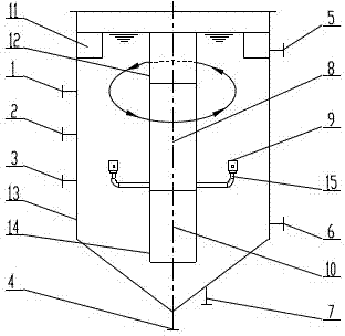
[0013] A swirling air flotation device, comprising a vertical cylinder 13, one side of the cylinder 13 is provided with a water inlet 1, an air inlet 2, and a return opening 3, and the bottom end of the cylinder 13 is provided with a slag discharge port 4 and Vent 7, the other side of the cylinder 13 is provided with a water outlet 6 near the bottom, and an overflow port 5 is provided near the top. The center of the cylinder 13 is provided with a central cylinder, which is divided into upper, middle and lower chambers. The upper chamber 12 is a slag collection tank, and the pipes in the upper chamber 12 are connected to the slag outlet 4. The middle chamber 8 has a built-in microbubble generator, and several branch pipes 15 are distributed around the middle chamber 8. The branch pipes The end of 15 is provided with an injector 9, and the lower chamber 10 is a sump. An overflow tank 11 is provided at the overflow port 5 . The pipeline of the water inlet 1 is arranged tangentia...


PUM


Abstract

The invention relates to a cyclone air flotation apparatus, and belongs to the field of water treatments. The cyclone air flotation apparatus comprises a vertical cylinder, wherein one side of the cylinder is provided with a water inlet, a gas inlet and a reflux port, the bottom end of the tapered bottom of the cylinder is provided with a residue discharge port and an emptying port in a parallel manner, the other cylinder side close to the bottom is provided with a water outlet, the position close to the top end is provided with an overflow port, a center cylinder is arranged in the center of the cylinder and is divided into an upper chamber, a middle chamber and a lower chamber, the upper chamber is a residue collection tank, an upper chamber pipeline is connected with the residue discharge port, a micro gas bubble generator is arranged inside the middle chamber, the periphery of the middle chamber is distributed with a plurality of branch pipelines, the end portions of the branch pipelines are provided with injectors, the lower chamber is a water collection tank, and the residue discharge port on the bottom and the overflow port on the upper portion are normally opened during running. According to the present invention, after entering the air flotation cylinder, water requiring a treatment performs a cyclone movement on the water inlet horizontal level in the cylinder by using the hydrodynamic force so as to make the light phase suspension granules continuously agglomerate to the center, and rapidly move upward and flow into the residue collection tank under the effect of elevation buoyancy of micro gas bubbles injected by the injectors distributed on the periphery of the built-in micro gas bubble generator so as to achieve water purification and pollutant collection and treatment.

Description

technical field [0001] The invention relates to the field of water treatment, in particular to the field of cyclone air flotation treatment. Background technique [0002] In water supply and wastewater treatment, especially industrial wastewater treatment, except for heavy particle pollutants, which are settled by sedimentation, almost all light suspended solids and dissolved pollutants are mostly separated and purified by air flotation with chemical addition and flocculation. of. The traditional advection air flotation tank is almost used in water treatment projects all over the country. However, due to low technical content, high power consumption, high treatment cost, and large investment and land occupation, not only is it difficult to achieve the water output target of physical and chemical pretreatment, but also it has become one of the key monitoring targets for carbon emissions due to high power consumption. [0003] The technology of the present invention is curre...

Claims


Application Information

Patent Timeline
Patent Type & Authority Applications(China)
IPC IPC(8): C02F1/24
Inventor 蒋惟光
Owner YAZHOU ENVIRONMENTAL PROTECTION YIXING CITY
Learn More