
Shear type expansion anchor rod and application thereof

An expansion bolt and expansion plate technology, which is used in the installation of bolts, sheet pile walls, mining equipment, etc., can solve the problems of abandoned foundations, inability to use adhesives, reduced work efficiency and construction progress, etc. Good effect, improve the effect of anchoring effect

Active Publication Date: 2014-04-02
裴春光
View PDF8 Cites 33 Cited by
  • Summary
  • Abstract
  • Description
  • Claims
  • Application Information

AI Technical Summary

Problems solved by technology

[0003] 1. Expansion tubular anchors and expansion shell anchors. Due to their own structural defects, the opening and closing degree and stiffness of the expansion end of the anchor head and the force after expansion are limited due to their own structural defects. The stable solid layer realizes reliable expansion consolidation or locking, poor pull-out resistance, weak suspension and clamping force;
[0004] 2. In order to make up for the above defects, there have been grouting anchors and injection expansion anchors. This type of anchor is made by stringing together a number of loose or fragmented layers and filling the gaps with slurry and increasing the anchorage and anchorage. The overall friction of the matrix hole wall realizes the so-called "composite beam" or "arch effect". State solid layer), taking a step back, even if the so-called "composite beam" or "arch effect" can be expected to work, the clamping force that strings loose or fragmented layers together still requires strong opening and closing and rigidity of the expansion end of the anchor rod , otherwise the nut at the end of the anchor rod cannot tighten them, and the anchor rod can only play the role of "pin", and cannot effectively realize the role of "composite beam" or "arch effect";
[0005] 3. In order to solve the problem of anchor head consolidation, people have developed an adhesive method. It is obvious that adhesives cannot substantially solve the "rooting" problem of the anchor, that is, it is impossible to make the anchor head and the matrix The firm and reliable consolidation or locking of the elastic zone or the stable solid layer, especially for the suspension or permanent anchoring of the upper part of the surrounding rock, or must reflect the immediate anchoring effect, while the adhesive needs a curing period, and the adhesive has no effect on the application environment Adhesive adhesives cannot be used at all under conditions such as wet or soft sand and gravel layers or poorly cleaned holes, not to mention the negative reactions of adhesives to different application objects and service life. predict;
[0006] 4. In order to make up for the inability to "take root" or the unreliability of "rooting", people have adopted the method of increasing the anchoring density to distribute the weight or displacement force of the loose layer to more anchor rods, which greatly increases the labor intensity. , reduced work efficiency and construction progress, and greatly increased the overall cost. However, the problem of "rooting" the anchor rod has not been resolved. , treat the symptoms but not the root cause, and if it is not done well, it will disturb or destroy the surrounding stable layer

Method used


Image

  • Shear type expansion anchor rod and application thereof
  • Shear type expansion anchor rod and application thereof
  • Shear type expansion anchor rod and application thereof

Examples


Embodiment 1

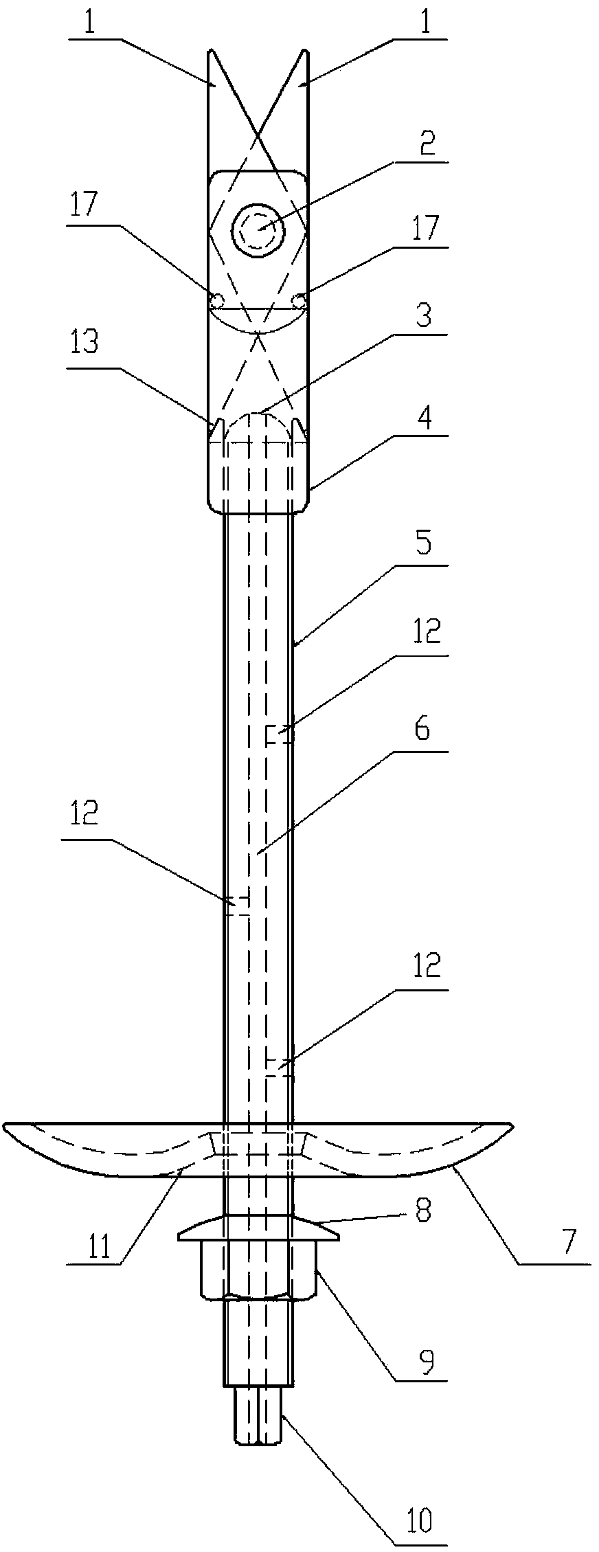
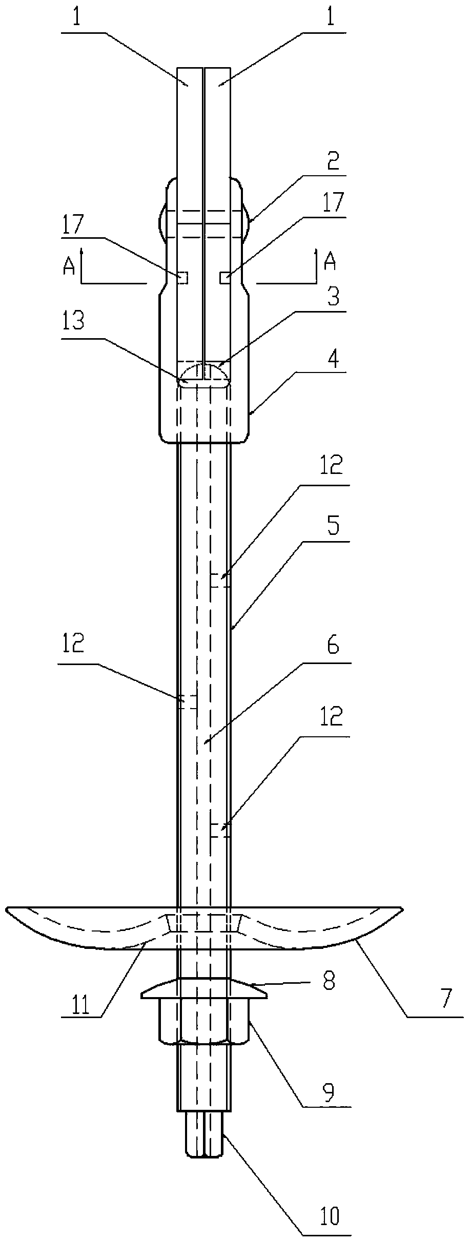
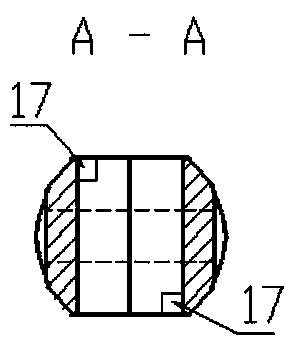
[0090] Such as figure 1 , 2 , 4, the present invention includes a lug nut support 4 and a screw 5 matched with the lug nut support 4, the lug nut support 4 has two oppositely arranged support plates, and hinge holes are arranged on the top of the support plate , the riveting shaft 2 is installed in the hinged hole; the two expansion plates 1 are combined and embedded between the two support plates of the lug nut bearing 4, and are hinged with the support plate through the riveting shaft 2; The inner edges and corners of the lower end slope of the expansion plate 1 contact, and the screw rod 5 can be screwed in to push the two expansion plates 1 to expand outwards respectively along the inner edges and corners of the lower end slope of the expansion plate 1 . Here, the distribution of the force points that push the expansion plate falls symmetrically on the arc surface of the screw end or the diameter line of the hemispherical head, or the projection line of the merged surface...

Embodiment 2

[0103] Such as Figure 7 , 8 As shown in and 9, the present embodiment is basically the same as Embodiment 1, the difference is that, in order to be suitable for anchoring with higher strength, the bridge 14 is consolidated at the upper ends of the two support plates of the lug nut bearing 4, so that the two The support plate is more stable and reliable; at the same time, the crossing bridge 14 is tapered, and its advantage is that the present invention can be directly driven into or pressed into the softer anchor matrix, and the function of the chisel head is integrated, including the head of the crossing bridge. And set the self-tapping thread on the side. Of course, the upper end surface of the bridge can be arc-shaped or flat, and anti-slip patterns or teeth can be set on the end surface.

[0104] Such as Figure 7 , 8 As shown in and 9, the expansion plate embedded in the lug nut support 4 is transformed into a special-shaped expansion plate 15 with one end being arc-sh...

Embodiment 3

[0106] Such as Figure 10 , 11 , 14, the present embodiment is basically the same as Embodiment 2, the difference is that, in order to be more convenient to use, the pre-drilling step is omitted, and a drill bit 18 is set on the upper end of the lug nut support 4, and the drill bit 18 is screwed on the belt. On the thread bridge 26. In this way, the present invention can be drilled directly into the anchor matrix by self-cutting.

[0107] At the same time, in order to facilitate the operations of drill bit drilling and anchorage expansion without interfering with each other, a self-locking device A1 is provided at the matching part of the screw rod and the lug nut support. Specifically, two structural schemes are provided:

[0108] The first option: if Figure 12 , 13 And shown in 34, self-locking device A1 comprises the dead bolt chamber 23 that the head side of screw rod 5 is provided with, dead bolt 29 and stage clip 24 are installed in the dead bolt chamber 23, open l...


PUM


Abstract

The invention provides a shear type expansion anchor rod which can be effectively applied to anchoring or reinforcing or fixing of loose and unstable layers in the engineering of tunnels, slope protection, foundation pits, dams, exploitation and the like, and an application method thereof. The shear type expansion anchor rod comprises a lug-containing nut support the upper part of which is hinged with expansion plates, and a screw rod matched with the lug-containing nut support, wherein the top end part of the screw rod is a cambered surface or semispherical head; the cambered surface or semispherical head on the top end part of the screw rod is contacted with the inner side corner of a bevel plane on the lower end part of each expansion plate; the inner side corner of the bevel plane on the lower end part of each expansion plate can be directly driven to continuously push each expansion plate to strut in a shear form towards an outer side by rotating the screw rod; a support plate and a nut matched with the support plate are sleeved at the lower end of the screw rod. The shear type expansion anchor rod has the advantages of simple and skilful structure, easiness in machining and manufacturing, convenience and reliability in use and low machining cost.

Description

technical field [0001] The invention relates to an anchor rod in the technical field of anchoring, in particular to a scissor expansion anchor rod and its application method. Background technique [0002] In the implementation of projects such as mines, tunnels, slope protection, foundation pits, and dams, it has become an application trend to use anchor bolts to reinforce loose and unstable layers. The existing anchor bolts include the following types: [0003] 1. Expansion tubular anchors and expansion shell anchors. Due to their own structural defects, the opening and closing degree and stiffness of the expansion end of the anchor head and the force after expansion are limited due to their own structural defects. The stable solid layer realizes reliable expansion consolidation or locking, poor pull-out resistance, weak suspension and clamping force; [0004] 2. In order to make up for the above defects, there have been grouting anchors and injection expansion anchors. Th...

Claims


Application Information

Patent Timeline
Patent Type & Authority Applications(China)
IPC IPC(8): E21D21/00E02D5/74
Inventor 裴志胜裴春光
Owner 裴春光
Learn More