Method for dynamically controlling furnace temperature of heating furnace based on time sensitivity

A technology of dynamic heating and control method, applied in the field of metallurgy

Inactive Publication Date: 2014-04-02
SHANGHAI MEISHAN IRON & STEEL CO LTD
View PDF3 Cites 9 Cited by
  • Summary
  • Abstract
  • Description
  • Claims
  • Application Information

AI Technical Summary

Problems solved by technology

[0003]1. This scheme is only applicable to the steel rolling environment where the target temperature of the steel grade does not change much and runs continuously; When the manufacturing environment changes and the furnace is shut down and waiting for rolling, this technical solution does not take into account the residence time of the slab in the furnace, and its scale and energy consumption are larger than the optimal solution, so its implementation effect is not ideal
[0004]2. In this technical solution, when the target temperature of each segment needs to be controlled, the actual furnace temperature setting Not adjusted accordingly, so its implementation is suboptimal
[0005]3. For special steel grades, different heating methods, such as rapid heating and heat preservation, cannot be distinguished in different heating sections, so that the plate The billet has shortcomings such as overburning or insufficient soaking, so its implementation effect is not ideal

Method used


Image

  • Method for dynamically controlling furnace temperature of heating furnace based on time sensitivity
  • Method for dynamically controlling furnace temperature of heating furnace based on time sensitivity
  • Method for dynamically controlling furnace temperature of heating furnace based on time sensitivity

Examples


Embodiment 1

[0021] Each table is graded according to steel type and temperature (every 50°C).

[0022] Specific heat calculation:

[0023] hour

[0024] hour

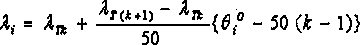
[0025] When ( k = 1~27 )

[0026]

[0027] in, : Average temperature of slab (°C); : Average specific heat (Kcal / kg℃); : Specific heat in the table (Kcal / kg℃); : slab identification; : Specific heat stratification level in the table

[0028] Calculation of heat transfer coefficient

[0029] hour

[0030] hour

[0031] When ( k = 1~27 )

[0032]

[0033] in, : Average temperature of slab (°C); : Average thermal conductivity (Kcal / mhr℃); : thermal conductivity in the table (Kcal / mhr℃); : slab identification; : Specific heat stratification level in the table

[0034] Step 3: Calculate the average physical parameters of the slab in each section according to the predicted shortest furnace time of the slab, the actual temperature of the slab and the physical length of each section of...


PUM


Abstract

The invention relates to a method for dynamically controlling the furnace temperature of a heating furnace based on time sensitivity. The method comprises the following steps: (1) dynamically calculating the minimum in-furnace time of a plate blank according to the in-furnace position and discharging rhythm of the plate blank, the heating capacity of the heating furnace and the movement information maximum value of a stepping beam; (2) retrieving the specific heat capacity of the heat conductivity of the plate blank according to the actual in-furnace temperature of the plate blank to obtain physical plate blank parameters corresponding to the actual temperature of the plate blank; (3) calculating average physical parameters of the plate blank in each section; (4) predicting the temperature of the plate blank reaching the section end, and calculating the furnace temperature sensitivity of the plate blank; (5) calculating the maximum temperature rise rate of the plate blank under the condition of different furnace temperatures according to the thermal expansion coefficient, stress and elastic modulus of the plate blank; (6) establishing an optimum furnace temperature setting target function, and then controlling the furnace temperature according to the optimum furnace temperature setting target function, wherein the constraint condition is an equivalence relation established according to the steps (4, 5 and 6). According to the method, the temperature rise rate of the furnace temperature can be dynamically controlled, so that over-heating or insufficient soaking of the plate blank is avoided.

Description

Technical field: [0001] The invention relates to a method for controlling the temperature of a dynamic heating furnace based on time sensitivity, and belongs to the technical field of metallurgy. Background technique: [0002] In the prior art, the temperature calculation parameters are set corresponding to each type of steel, and the furnace temperature setting value is set according to the temperature calculation parameters. This scheme has the following problems: [0003] 1. This scheme is only applicable to the steel rolling environment where the target temperature of the steel grade does not change much and runs continuously; for the steel grade target changes greatly, new steel grades appear, the rolling environment changes, and the furnace is shut down and waiting for rolling. Because the plan does not take into account the residence time of the slab in the furnace, its iron oxide scale and energy consumption are larger than the optimal plan, so its implementation e...

Claims


Application Information

Patent Timeline
Patent Type & Authority Applications(China)
IPC IPC(8): F27D19/00
Inventor 葛晓余金鹏盛磊周心富袁军赖森贞李美华程林肖瑶马克步
Owner SHANGHAI MEISHAN IRON & STEEL CO LTD
Why Eureka
Try Eureka