
Robot navigation method based on three electromagnetic sensors

An electromagnetic sensor and navigation method technology, applied in the field of robot navigation, can solve problems such as low precision, many parameters, and complex design, and achieve the effects of improving accuracy, reducing the probability of introducing random errors, and simplifying design and measurement

Inactive Publication Date: 2014-04-02
BEIJING UNIV OF TECH
View PDF12 Cites 24 Cited by
  • Summary
  • Abstract
  • Description
  • Claims
  • Application Information

AI Technical Summary

Problems solved by technology

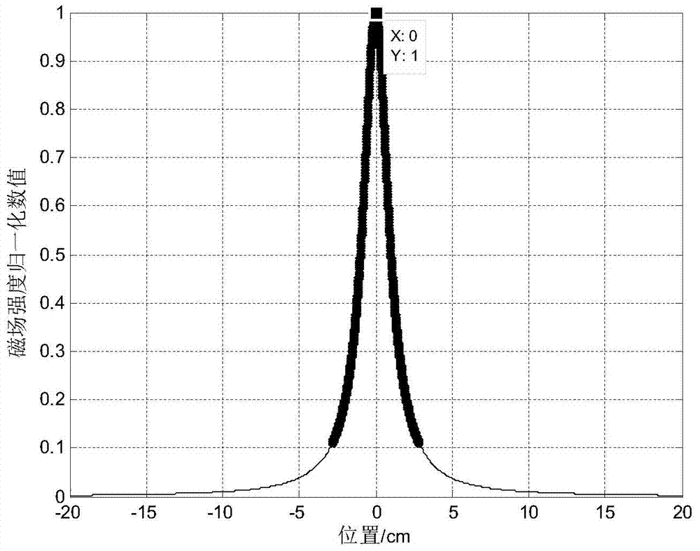
[0004] Aiming at the problems of low precision, many parameters and complicated design in navigation using double symmetrical electromagnetic sensors, the present invention proposes a robot navigation method based on three electromagnetic sensors, which no longer uses the difference of magnetic field strength at symmetrical positions to represent the relative position of the robot. The position of the electromagnetic track, but the use of the magnetic field strength and the position curve's strict axisymmetric characteristics to represent the position of the robot relative to the electromagnetic track, simplifies the number of boundary threshold parameters, parameter design methods and the calibration process of the center position, and improves the electromagnetic navigation accuracy of the robot

Method used


Image

  • Robot navigation method based on three electromagnetic sensors
  • Robot navigation method based on three electromagnetic sensors
  • Robot navigation method based on three electromagnetic sensors

Examples


Embodiment Construction

[0027] The present invention will be further described below in conjunction with the accompanying drawings and specific embodiments.

[0028] The robot navigation device includes an electromagnetic track, an electromagnetic sensor, a signal amplifier and a mobile controller, wherein,

[0029] The electromagnetic track is laid with enameled wire. The diameter of the enameled wire is 0.3mm. There is a sinusoidal alternating current with a frequency of 20kHz and a magnitude of 100mA±20mA in the enameled wire, which generates a 20kHz alternating electromagnetic field around the electromagnetic track.

[0030] The electromagnetic sensor consists of three 10mH "I"-shaped inductance coils, arranged in a straight line and horizontally, and the distance from the left end to the right end is 10cm, such as Figure 5 , 6 shown. Each inductor is connected in parallel with a 6.8nF capacitor to form an LC tank with a resonant frequency of 20kHz. Since the frequency of the electromagnetic ...


PUM


Abstract

The invention discloses a robot navigation method based on three electromagnetic sensors. The method aims to overcome defects such as low precision, a plenty of parameters and complex design in bisymmetric electromagnetic sensor navigation. The robot navigation method disclosed by the invention comprises the following steps: taking difference of a value and a maximum value of a middle sensor as the size of a robot to deviate from a track, and judging the direction of the robot which deviates from an electromagnetic track according to the plus or minus of a difference value of a left sensor and a right sensor and the difference of an electromagnetic track deviating direction threshold value, synthesizing the track deviating size and the track deviating direction as an error signal of a robot mobile controller to control the robot to move in an error reducing direction, thereby realizing electromagnetic navigation of the robot. The method simplifies the parameters design and measurement such as a boundary threshold value, reduces the probability of introducing random errors, avoids influences due to asymmetry of sensor performances, and improves the precision of the robot electromagnetic navigation.

Description

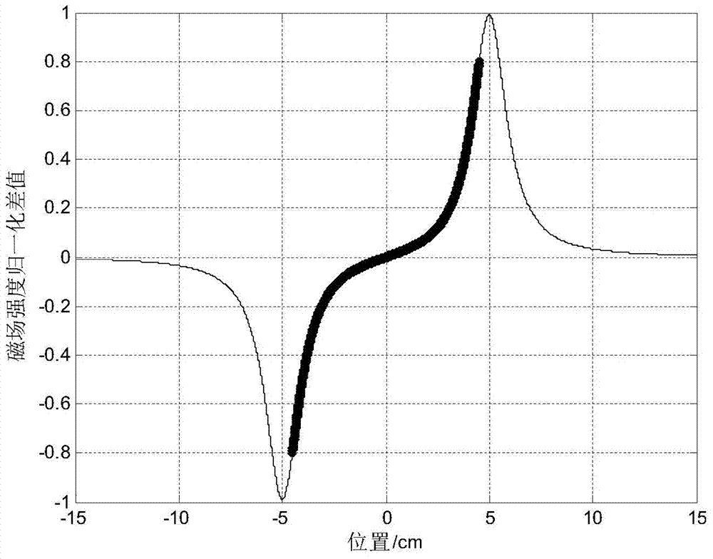
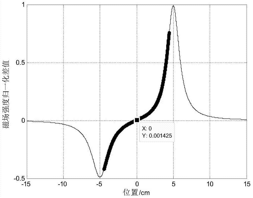
technical field [0001] The invention belongs to the field of robots, and relates to a robot navigation method, which uses three electromagnetic sensors to detect the size and direction of a robot's deviation from an electromagnetic track, and guides the robot to move along the electromagnetic track. Background technique [0002] At present, most of the electromagnetic track detection devices used in robots are an even number of "I"-shaped inductors, which are horizontally and symmetrically distributed on both sides above the track, and the difference in magnetic field strength detected by the symmetrically positioned electromagnetic sensors is used to determine the size of the deviation from the track. . In an ideal state, the parameters of the left and right symmetrical position sensors are strictly the same. At this time, the difference between the sensor’s detected magnetic field strength and the position is as follows: figure 1 shown. The bold black curve can represent...

Claims


Application Information

Patent Timeline
IPC IPC(8): G05D1/02
Inventor 董政胤贾松敏李秀智
Owner BEIJING UNIV OF TECH
Learn More