Feed antenna applied to 94 GHz passive millimeter wave imaging system
A millimeter-wave imaging, passive technology, applied in the field of feed antennas, can solve the problems of reduced spatial resolution and too large aperture of imaging systems, and achieve the effects of good radiation performance, moderate gain, and easy processing.
- Summary
- Abstract
- Description
- Claims
- Application Information
AI Technical Summary
Problems solved by technology
Method used
Image
Examples
specific Embodiment approach 1
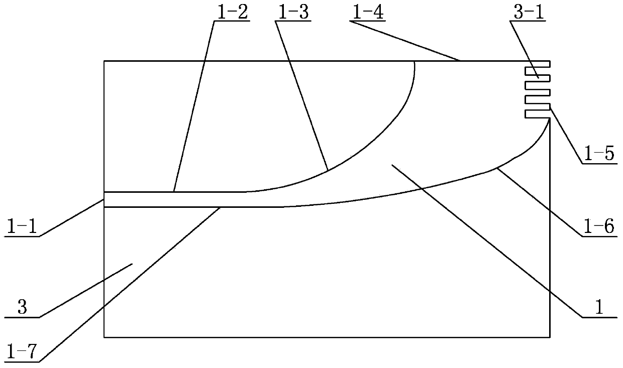
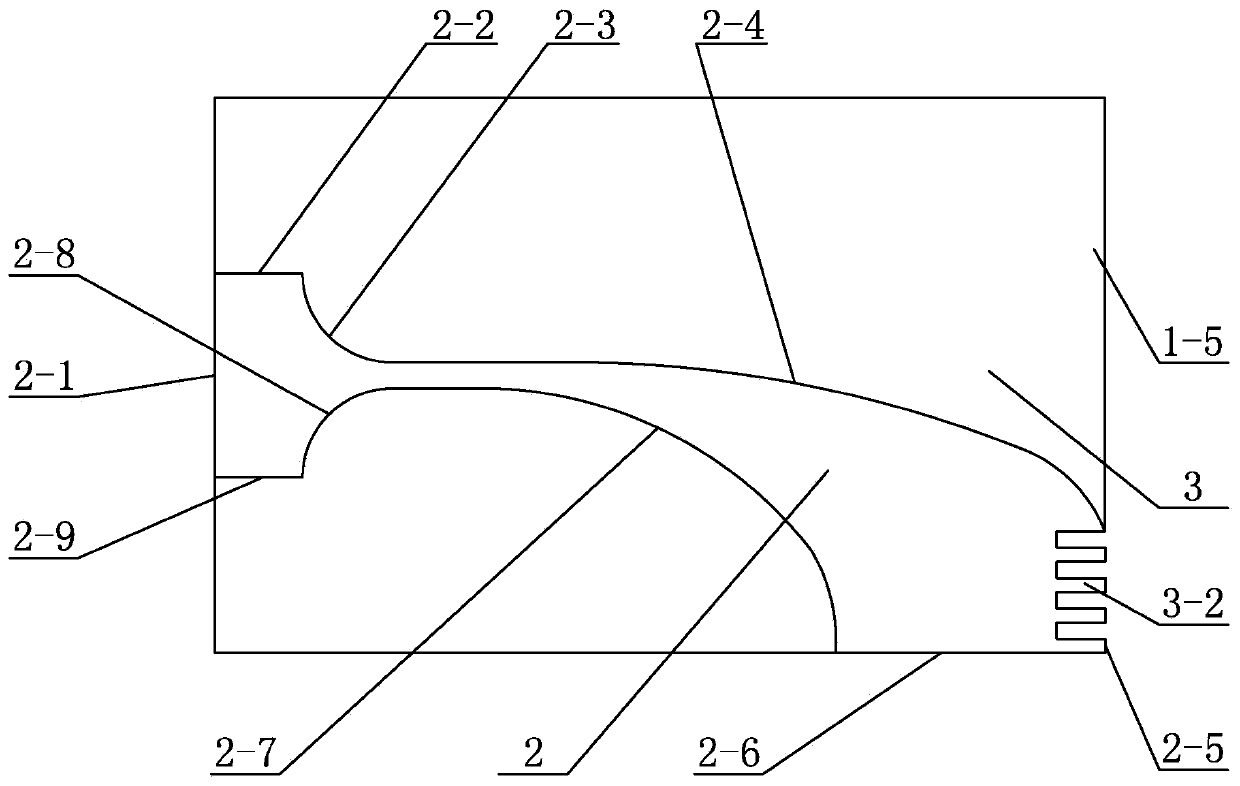
[0007] Specific implementation mode one: combine figure 1 and figure 2 Describe this embodiment. A feed antenna for a 94GHz passive millimeter-wave imaging system described in this embodiment includes a front metal floor 1, a back metal floor 2, and a dielectric board 3. The dielectric board 3 is a rectangular board, and the front metal floor 1 is printed on the upper part of the front of the dielectric board 3, and the back metal floor 2 is printed on the lower part of the back of the dielectric board 3. The upper part of one end of the dielectric board 3 is provided with a first sawtooth structure 3-1, and the front metal floor 1 and the first sawtooth structure 3-1 1, the lower part of one end of the dielectric board 3 is provided with a second sawtooth structure 3-2, and the back metal floor 2 is connected to the second sawtooth structure 3-2.
[0008] The model of the dielectric board 3 in this embodiment is Rogers RT5870.
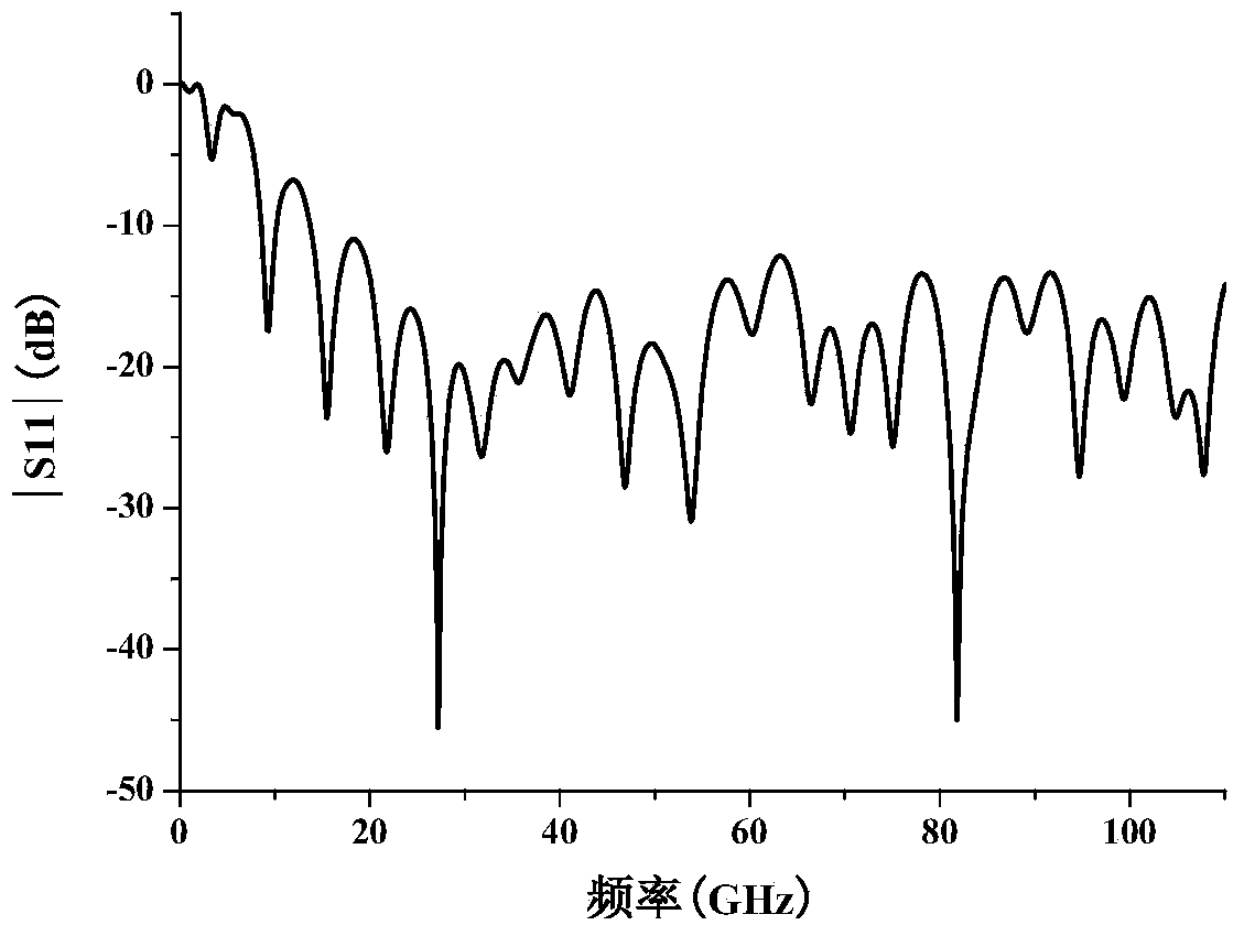
[0009] From Figure 3 to Figure 5 It can be...
specific Embodiment approach 2
[0010] Specific implementation mode two: combination figure 1 and figure 2 Describe this embodiment. The front metal floor 1 of a feed antenna applied to a 94GHz passive millimeter-wave imaging system described in this embodiment is composed of the first vertical side 1-1 of the front metal floor and the first horizontal side of the front metal floor. and The second horizontal side 1-7 of the front metal floor is connected end-to-end to form a closed polygon, and the first vertical side 1-1 of the front metal floor coincides with the vertical side of the other end of the dielectric board 3, and the second horizontal side 1 of the front metal floor -4 coincides with the top edge of the medium plate 3, and the first sawtooth edge 1-5 of the front metal plate coincides with the first sawtooth structure 3-1.
[0011] The technical effect of this embodiment is: set in this way, the first arc edge 1-3 of the front metal floor and the second arc edge 1-6 of the front metal floor f...
specific Embodiment approach 3
[0012] Specific implementation mode three: combination figure 1 and figure 2 Describe this embodiment. The back metal floor 2 of a feed antenna applied to a 94GHz passive millimeter-wave imaging system described in this embodiment is composed of the first vertical side 2-1 of the back metal floor and the first horizontal side of the back metal floor. 2-2, the first arc side of the back metal floor 2-3, the second arc side of the back metal floor 2-4, the first zigzag side of the back metal floor 2-5, the second horizontal side of the back metal floor 2-6, A closed polygon formed by connecting the third arc edge 2-7 of the back metal floor, the fourth arc edge 2-8 of the back metal floor, and the third horizontal edge 2-9 of the back metal floor sequentially from end to end, and the back metal floor is first vertical Side 2-1 coincides with the vertical side of the other end of the medium board 3, the first sawtooth side 2-5 of the back metal floor coincides with the second s...
PUM
 Abstract
Description
Claims
Application Information
 - R&D
- Intellectual Property
- Life Sciences
- Materials
- Tech Scout
- Unparalleled Data Quality
- Higher Quality Content
- 60% Fewer Hallucinations
Browse by: Latest US Patents, China's latest patents, Technical Efficacy Thesaurus, Application Domain, Technology Topic, Popular Technical Reports.
© 2025 PatSnap. All rights reserved.Legal|Privacy policy|Modern Slavery Act Transparency Statement|Sitemap|About US| Contact US: help@patsnap.com


