An Access System of Static Var Generator
A static reactive power, access system technology, applied in flexible AC transmission systems, reactive power adjustment/elimination/compensation and other directions, can solve problems such as protection malfunction, interference with grid equipment, large peak value, etc., to avoid impact.
- Summary
- Abstract
- Description
- Claims
- Application Information
AI Technical Summary
Problems solved by technology
Method used
Image
Examples
Embodiment 1
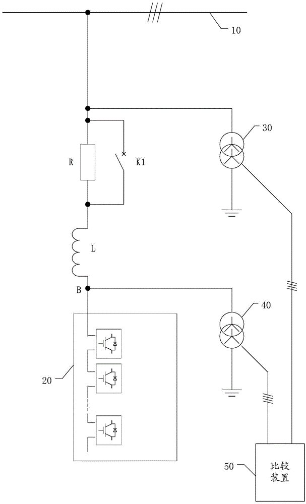
[0036] figure 1 A static var generator access system provided by the embodiment of this application.
[0037] Such as figure 1 As shown, the access system disclosed in this embodiment includes a current limiting resistor R, a closing switch K1 , a first sensor 30 , a second sensor 40 and a comparison device 50 . Among them: one end of the current-limiting resistor R is connected to the high-voltage bus 10 of the power grid, and the other end is connected to the series reactor L of the static var generator 20; the closing switch K1 is connected in parallel with the current-limiting resistor R, that is, the closing switch K1 The two ends of the two ends of the current-limiting resistor R are connected respectively; the first sensor 30 is connected with the high-voltage bus 10; the second sensor 40 is connected with the power output terminal B of the static var generator 20; the comparison device 50 is respectively connected with The first sensor 30 and the second sensor 40 are...
Embodiment 2
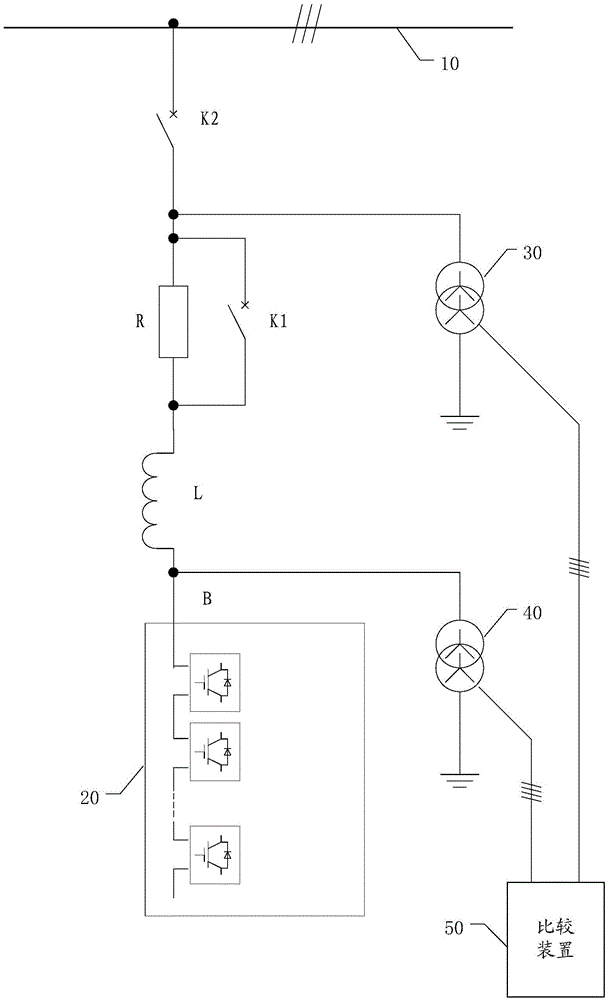
[0047] figure 2 A structural diagram of a static var generator access system provided by another embodiment of the present application.
[0048] Such as figure 2 As shown, the access system provided in this embodiment is based on the previous embodiment with the addition of a grid switch K2. The grid switch K2 is arranged between the series resistor R and the high voltage bus 10 of the grid.
[0049] The grid switch K2 is used to connect or disconnect the electrical connection between the series resistor R and the high-voltage bus 10 to input current to the static var generator 20 to start charging or to disconnect the static var generator 20 from the grid.
[0050] The grid switch K2 is preferably a contactor or a circuit breaker.
Embodiment 3
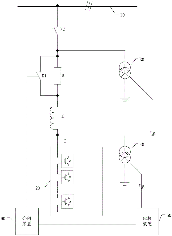
[0052] image 3 It is a structural diagram of a static var generator access system disclosed in another embodiment of the present application.
[0053] Such as image 3 As shown, the access system disclosed in this embodiment adds a closing device 60 on the basis of the previous embodiment. The closing device is respectively connected with the closing switch K1 and the comparing device 50 .
[0054] The closing device 60 is used to control the closing switch K1 to close according to the closing signal output by the comparing device 50 .
[0055] When the comparison device 50 outputs a closing signal, it indicates that the frequency, amplitude and phase of the voltages at the two points are consistent, and the closing device 60 controls the closing switch K1 to close, and connects the static var generator 20 to the power grid.
[0056] The additional closing device 60 can replace the manual closing operation, increasing the degree of automation.
[0057] In the above embodi...
PUM
 Abstract
Description
Claims
Application Information
 - R&D
- Intellectual Property
- Life Sciences
- Materials
- Tech Scout
- Unparalleled Data Quality
- Higher Quality Content
- 60% Fewer Hallucinations
Browse by: Latest US Patents, China's latest patents, Technical Efficacy Thesaurus, Application Domain, Technology Topic, Popular Technical Reports.
© 2025 PatSnap. All rights reserved.Legal|Privacy policy|Modern Slavery Act Transparency Statement|Sitemap|About US| Contact US: help@patsnap.com


