Copper rod manufacturing method and milling machine suitable for copper rod manufacturing method and capable of scoring

A manufacturing method and technology of copper rods, applied to milling machine equipment, manufacturing tools, details of milling machine equipment, etc., can solve the problems of high proportion of surface defects and large differences in ductility in the circumferential direction, etc., and achieve the effect of less proportion of defects

Inactive Publication Date: 2014-04-09
XINXING PIPES ZHEJIANG COPPER
View PDF6 Cites 9 Cited by
  • Summary
  • Abstract
  • Description
  • Claims
  • Application Information

AI Technical Summary

Problems solved by technology

[0003] The present invention aims to provide a copper rod production method with good consistency in the circumferential extension of the produced copper rod and a small proportion of surface defects and a scoring milling machine suitable for the method to solve the problem of existing copper rods. The rod manufacturing method has a high proportion of surface defects and a large difference in ductility in the circumferential direction

Method used


Image

  • Copper rod manufacturing method and milling machine suitable for copper rod manufacturing method and capable of scoring
  • Copper rod manufacturing method and milling machine suitable for copper rod manufacturing method and capable of scoring
  • Copper rod manufacturing method and milling machine suitable for copper rod manufacturing method and capable of scoring

Examples


Embodiment 1

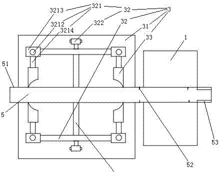
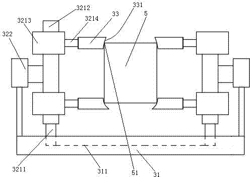
[0027] Example 1, see figure 1 , A scoring milling machine, including a milling machine 1 and a scoring mechanism 3. The milling machine 1 is an existing milling machine.

[0028] The scoring mechanism 3 is located on the feed side of the milling machine 1. The scoring mechanism 3 includes a base plate 31, a blade driving mechanism 32 and a blade 33. The base plate 31 is provided with a sliding groove 311. The blade driving mechanism 32 includes a pair of blade fixing frames 321 and a fixing frame driving cylinder 322. A pair of blade holders 321 are located on both radial sides of the copper rod blank 5. The blade holder 321 includes a sliding rod 3212 extending in the up and down direction and a knife seat 3213 slidably connected to the sliding rod. The blade 33 is connected to the knife holder 3213 by a double-headed screw 3214. The blade edges 331 located on both radial sides of the copper rod blank 5 face the copper rod blank 5. The cylinder body of the fixed frame dri...

Embodiment 2

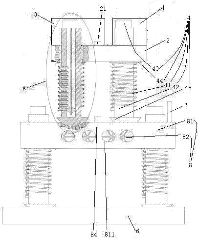
[0037] Example two, see image 3 The difference from the first embodiment is that it also includes a mounting seat 2, a floating raft 8 and a base 6 distributed in order from top to bottom. Both the milling machine 1 and the scoring mechanism 3 are fixed on the mounting base 2. The mounting base 2 is connected to the floating raft 8 through a number of vibration isolators 4. The floating raft 8 is connected to the base 6 through a number of vibration isolators 4. Specifically, there are 8 vibration isolators 4 (only 4 can be seen in the figure). Four of the eight vibration isolators 4 are used to support the mounting base 2 on the floating raft 8, and the other four vibration isolators are used to support the floating raft 8 on the base 6. The vibration isolator connecting the mounting base 2 and the floating raft 8 is staggered from the vibration isolator connecting the floating raft 8 and the base 6. The broadband vibration transmission between the mounting base 2 and the ...

Embodiment 3

[0052] The third embodiment, the difference from the second embodiment is: see Figure 8 End caps 829 are provided at both ends of the upper deformation channel 825 and the lower deformation channel 827. The upper inclined support plate of the upper inclined support plate 824 located between adjacent upper deformation channels 825, the lower inclined support plate of the lower inclined support plate 826 located between adjacent lower deformation channels 827, and the middle base plate 822 are located adjacent to each other. A damping channel 820 is provided on the part between the upper deformation channel and the lower deformation channel. Both the upper deformation channel 825 and the lower deformation channel 827 are filled with liquid (the liquid is not shown in the figure). The upper deformation channel 825 and the lower deformation channel 827 are provided with energy absorbing rods 83 suspended in the liquid. The extension direction of the energy absorbing rod 83 is the...


PUM


Abstract

The invention relates to the technical field of copper rod processing, specifically to a milling machine capable of scoring. The milling machine comprises a mill and a scoring mechanism, wherein the scoring mechanism comprises four cutter blades and a cutter blade drive mechanism for driving the cutter blades to score scores on four edges of a copper rod billet. The copper rod manufacturing method comprises: 1, adopting a continuous casting process to produce a copper rod billet with a rectangular cross-section; 1.1, scoring scores circumferential extending and circumferential distributing along the copper rod billet circumference on four edges of the copper rod billet; 1.2, milling off the copper rod billet surface and the four edges of the copper rod billet to form chamfers, wherein swarfs break from the scoring position during the chamfer forming process through milling the edges of the copper rod billet so as to fall down; and 2, adopting a continuous rolling process to produce the semi-finished product copper rod with a round cross-section. A purpose of the present invention is to provide a copper rod manufacturing method and a milling machine capable of scoring, wherein the produced copper rod has characteristics of good circumferential extension uniformity and less surface defect proportion, such that the problems of high surface defect proportion and high circumferential extension difference of the existing copper rod can be solved.

Description

Technical field [0001] The invention relates to the technical field of copper rod processing, in particular to a copper rod manufacturing method and a scoring milling machine suitable for the method. Background technique [0002] The existing copper rod processing technology is to melt the copper block into copper water through a melting furnace, then use a continuous casting machine to cast the copper water into a copper rod blank with a rectangular cross section, and then use a continuous rolling mill to convert the copper rod blank Roll into a semi-finished copper rod with a circular cross-section (hereinafter referred to as the semi-finished copper rod as a copper rod), and finally process the surface treatment and packaging to obtain the product copper rod. The Chinese patent number is 2008101439769, the publication date is March 17, 2010, and the patent document titled "A manufacturing process of a low-oxygen copper rod" discloses a method for manufacturing a copper rod...

Claims


Application Information

Patent Timeline
Patent Type & Authority Applications(China)
IPC IPC(8): B21C37/04B23C3/00
Inventor 袁剑锋陈宗华翟建民孙冀阳杨鑫王宪军申海军张斌海郭红卫
Owner XINXING PIPES ZHEJIANG COPPER
Why Eureka
Try Eureka