Shaft part cutting and/or grinding processing clamp and processing method thereof

A technology for grinding processing and shaft parts, which is applied in the direction of grinding workpiece supports, machine tools designed for grinding the rotating surface of workpieces, manufacturing tools, etc., which can solve the problem of large processing errors, affecting work efficiency, and inconvenient processing of eccentric inner circles Or outer circle and other problems, to achieve the effect of widening the range of shaft diameter specifications, highlighting substantive features, and good application prospects

Inactive Publication Date: 2014-04-09
广西壮族自治区汽车拖拉机研究所有限公司
View PDF5 Cites 16 Cited by
  • Summary
  • Abstract
  • Description
  • Claims
  • Application Information

AI Technical Summary

Problems solved by technology

Due to high machining accuracy requirements, if a conventional three-jaw or four-jaw chuck is used to clamp workpieces in mass production, there are the following disadvantages: a. Each workpiece needs to use a dial indicator to find the center of the circle, which is cumbersome to operate and difficult to produce. Low efficiency; b. Low positioning accuracy and large processing error; C. It is inconvenient to process eccentric inner or outer circles
[0003] Some special

Method used


Image

  • Shaft part cutting and/or grinding processing clamp and processing method thereof
  • Shaft part cutting and/or grinding processing clamp and processing method thereof
  • Shaft part cutting and/or grinding processing clamp and processing method thereof

Examples


Embodiment 1

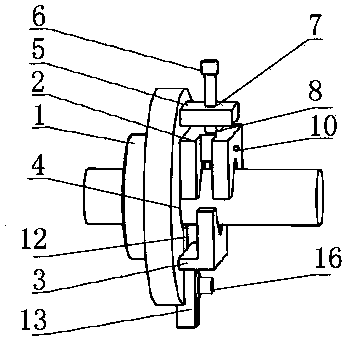
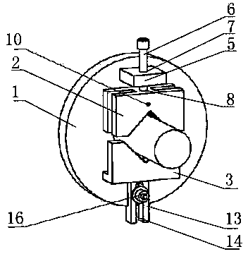
[0039] Such as Figure 6 As shown, on the universal cylindrical grinding machine, the outer circle of the processed parts is φ600-0.01 and the inner circle is φ600+0.01, and the coaxiality requirement with the reference outer circle of the part is φ80±0.01.

[0040] step:

[0041] 1. Install the chuck 1 of the fixture on the chuck of the universal cylindrical grinder, and use the dial indicator to find the center of the chuck 1;

[0042] 2. Put the part reference outer circle φ80±0.01 into the part through hole 4 in the middle of the chuck 1, place it between the upper clamping block 2 and the lower clamping block 3, adjust the position of the upper clamping block 2 and the lower clamping block 3, Clamp the outer circle of the part to φ80±0.01, and use the dial gauge to find the center of the outer circle of the part to φ80±0.01;

[0043] 3. Adjust the limit device to lock the upper clamping block 2 and the lower clamping block 3;

[0044] 4. Carry out grinding processing of ...

Embodiment 2

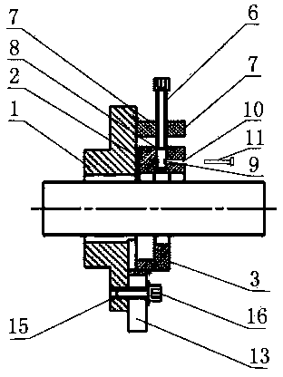
[0049] like Figure 7 As shown, on the universal cylindrical grinding machine, the outer circle of the processed part is φ600-0.01, and the eccentricity requirement of the part reference outer circle φ80±0.01 is e±0.05.

[0050] step:

[0051] 1. Install the chuck 1 of the fixture on the chuck of the universal cylindrical grinder, and use the dial indicator to find the center of the chuck 1;

[0052] 2. Put the part reference outer circle φ80±0.01 into the part through hole 4 in the middle of the chuck 1, place it between the upper clamping block 2 and the lower clamping block 3, adjust the position of the upper clamping block 2 and the lower clamping block 3, The outer circle of the clamping part is φ80±0.01, and at the same time, adjust the outer circle of the screw clamping part to φ80±0.01, and measure the runout of φ80±0.01 with a dial gauge until mmax-mmin=2 e (mmax-maximum run-out, mmin- minimum runout), tighten the bolt 16, lock the lower clamp 3, tighten the screw 1...


PUM


Abstract

The invention provides a shaft part cutting and/or grinding processing clamp and a processing method thereof. The clamp comprises a clamping disc, an upper clamping block and a lower clamping block, a part through hole is arranged in the middle of the clamping disc, the upper clamping block and the lower clamping block are mounted in a same radial direction of the clamping disc respectively and can be in linear feeding movement in the radial direction of the clamping disc, a limiting device is connected on the upper clamping block and the lower clamping block respectively and can limit position of the upper clamping block or the lower clamping block, a V-shaped opening is arranged on each of the upper clamping block and the lower clamping block, and the openings of the upper clamping block and the lower clamping block are arranged oppositely. The processing method utilizes the clamp, so that perfect circle direction or eccentricity of a part can be conveniently adjusted within an allowable range of the clamp, processing accuracy can be guaranteed within a dimensional tolerance range, and different processing condition requirements can be met. The shaft part cutting and/or grinding processing clamp is simple in structure, wide in application range and capable of meeting needs of processing of outer circles or inner circles of various shaft parts, and has good application prospect.

Description

technical field [0001] The invention relates to the field of machinery, in particular to a jig for cutting and / or grinding a shaft part and a processing method. Background technique [0002] At present, the inner or outer circle cutting and / or grinding of the shaft parts is performed on the universal cylindrical grinding machine, and the workpiece is usually clamped by three-jaw or four-jaw chucks. Due to the high machining accuracy requirements, if a conventional three-jaw or four-jaw chuck is used to clamp workpieces in mass production, there are the following disadvantages: a. Each workpiece needs to be centered with a dial indicator, which is cumbersome to operate and difficult to produce. Low efficiency; b. Low positioning accuracy and large processing error; C. It is inconvenient to process eccentric inner or outer circles. [0003] Some special fixtures for shaft parts have appeared in the prior art, but these special fixtures can only be used for one or several type...

Claims


Application Information

Patent Timeline
IPC IPC(8): B24B41/06B23Q3/00
CPCB24B5/02B23Q3/00B24B41/067
Inventor 许冠能
Owner 广西壮族自治区汽车拖拉机研究所有限公司
Why Eureka
Try Eureka