Detachable pipe wrench

A technology of pipe wrench and pliers, which is applied in the direction of wrench, wrench, manufacturing tools, etc. It can solve the problems of reducing the clamping effect, immobility, and increasing the workload of the operation, so as to improve the clamping effect, increase the service life, The effect of simple structure

Inactive Publication Date: 2014-04-09
SUZHOU QISHUO INFORMATION TECH CO LTD
View PDF5 Cites 1 Cited by
  • Summary
  • Abstract
  • Description
  • Claims
  • Application Information

AI Technical Summary

Problems solved by technology

[0003] Existing pipe wrench is generally provided with a pliers body on the head of the pliers handle to clamp the pipe, and its position cannot be moved, thereby pulling the pliers handle to make the pipe rotate, which can only be operated unilaterally by hand, so the rotation It is very cumbersome to loosen the pliers and turn again after turn

Method used


Image

  • Detachable pipe wrench
  • Detachable pipe wrench
  • Detachable pipe wrench

Examples


Embodiment

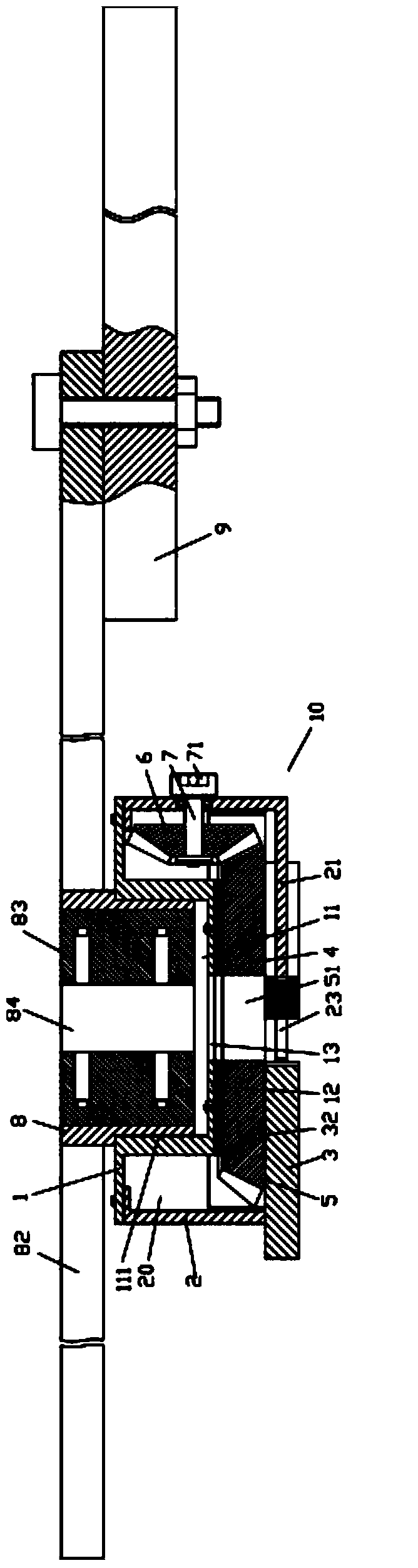
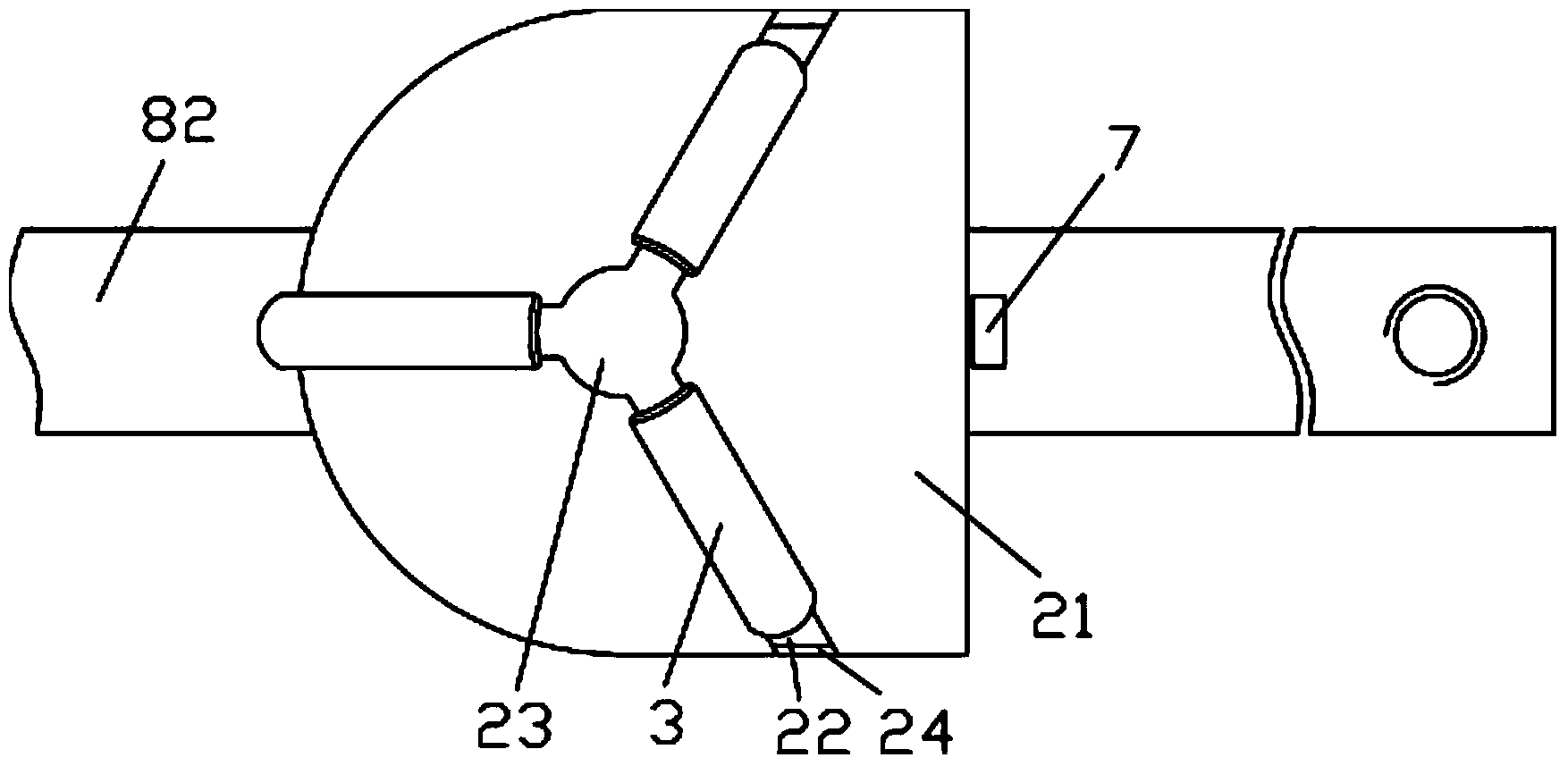
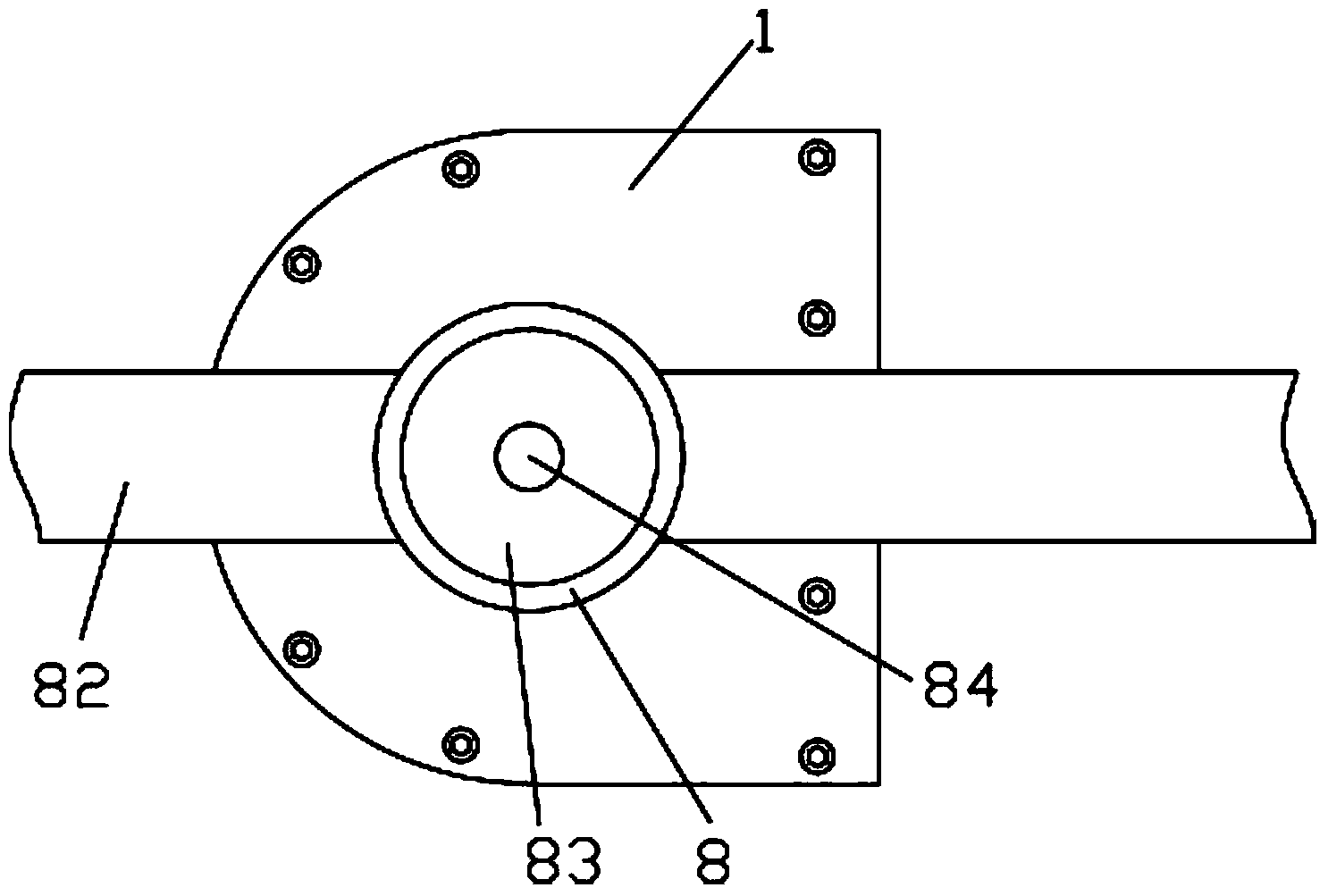
[0024] Example: see Figures 1 to 7 As shown, a detachable pipe wrench includes a pliers body 10, the pliers body 10 includes an upper shell 1 and a lower shell 2, the upper shell 1 is fixedly connected to the lower shell 2 by bolts, and the upper shell 1 and the inside of the lower housing 2 to form a gear cavity 20, the middle part of the upper housing 1 is concaved downward to form a circular groove 11, the upper bottom plate 12 of the circular groove 11 is formed with a circular through hole 13, the lower housing 2 Three elongated through grooves 22 and insertion holes 23 are formed on the bottom plate 21 of the bottom plate, the insertion holes 23 are at the center of the bottom plate 21, and the three elongated through grooves 22 are evenly distributed on the bottom plate 21 with the insertion holes 23 as the center. 23 communicates with each other, the tail end extends outwards and passes through the side of the bottom plate 21, the bottom of the side wall of the lower ...


PUM

PropertyMeasurementUnit
Diameteraaaaaaaaaa

Abstract

A detachable pipe wrench comprises a wrench body. The wrench body comprises an upper shell and a lower shell. A gear cavity is formed inside the upper shell and the lower shell. The middle of the upper shell is concaved downwards to form a circular groove, a circular through hole is formed in an upper bottom plate of the circular groove, three long through grooves and an inserting hole are formed in a bottom plate of the lower shell, three notches are formed in the bottom of the side wall of the lower shell, the notches are communicated with the tail ends of the long through grooves, long-strip-shaped grooves are formed in the two side walls of clamping blocks, and the two side walls of the long through grooves are inserted into the long-strip-shaped grooves in a sleeved mode. A Teflon layer is fixed on the lower bottom face of the upper bottom plate, the gear cavity is internally provided with a main bevel gear and a drive bevel gear which are meshed with each other, and the main bevel gear is arranged between the Teflon layer and the clamping blocks. The detachable pipe wrench is simple in structure, a user can hold two wrench arms to carry out double-hand operation by hands, efficiency is improved, the three clamping blocks and a circular elastic block are used for carrying out further clamping, the clamping effect is improved, and a pipe is prevented from skidding when rotating.

Description

Technical field: [0001] The invention relates to the technical field of pipe wrench structures, and more specifically relates to a detachable pipe wrench. Background technique: [0002] Pipe wrench is generally used to clamp and rotate steel pipe workpieces. Widely used in textile machinery industry. Clamp the tube and turn it to complete the connection. Its working principle is to convert the force of the clamp into the torque, and the greater the force used in the twisting direction, the tighter the clamp will be. [0003] Existing pipe wrench is generally provided with a pliers body on the head of the pliers handle to clamp the pipe, and its position cannot be moved, thereby pulling the pliers handle to make the pipe rotate, which can only be operated unilaterally by hand, so the rotation It is very troublesome to loosen the caliper body after turning once, clamp and turn again, especially when the pipe is rotated without effort, this operation increases the workload o...

Claims


Application Information

Patent Timeline
IPC IPC(8): B25B13/50
CPCB25B13/5058
Inventor 付淑珍
Owner SUZHOU QISHUO INFORMATION TECH CO LTD
Why Eureka
Try Eureka