Automatic feeding device

A technology of automatic feeding and transmission box, applied in the field of mechanical parts processing and manufacturing, can solve the problems of low degree of automation, low production efficiency, increase production cost, etc., and achieve the effect of stable conveying speed and low working noise.

Active Publication Date: 2014-04-09
WUXI BEST PRECISION MACHINERY
View PDF8 Cites 6 Cited by
  • Summary
  • Abstract
  • Description
  • Claims
  • Application Information

AI Technical Summary

Problems solved by technology

In the existing production enterprises, the transition of parts from the phosphating line to the powder spraying line is completely done manually. The degree of automation is low, the labor intensity is high, and the production efficiency is low, which cannot meet the needs of automation and mass production. It increases the production cost of the enterprise and is the biggest obstacle to the realization of automatic production in the production of enterprises

Method used


Image

  • Automatic feeding device
  • Automatic feeding device
  • Automatic feeding device

Examples


Embodiment Construction

[0031] The present invention will be further described below in conjunction with specific drawings and embodiments.

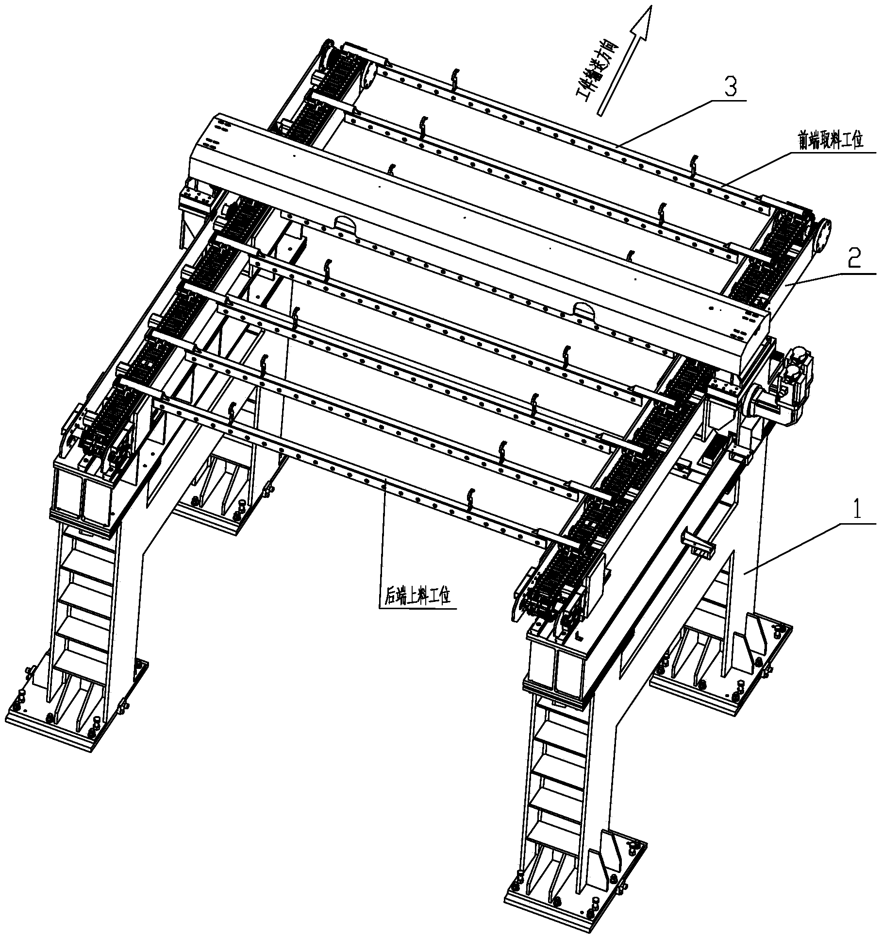
[0032] Such as figure 1 As shown, the automatic feeding device in the embodiment is an automatic equipment that realizes that the workpiece is automatically transported from the rear feeding station to the front reclaiming station. It is mainly composed of a bottom bracket part 1, an upper transmission part 2 and a conveying boom 3. composition.

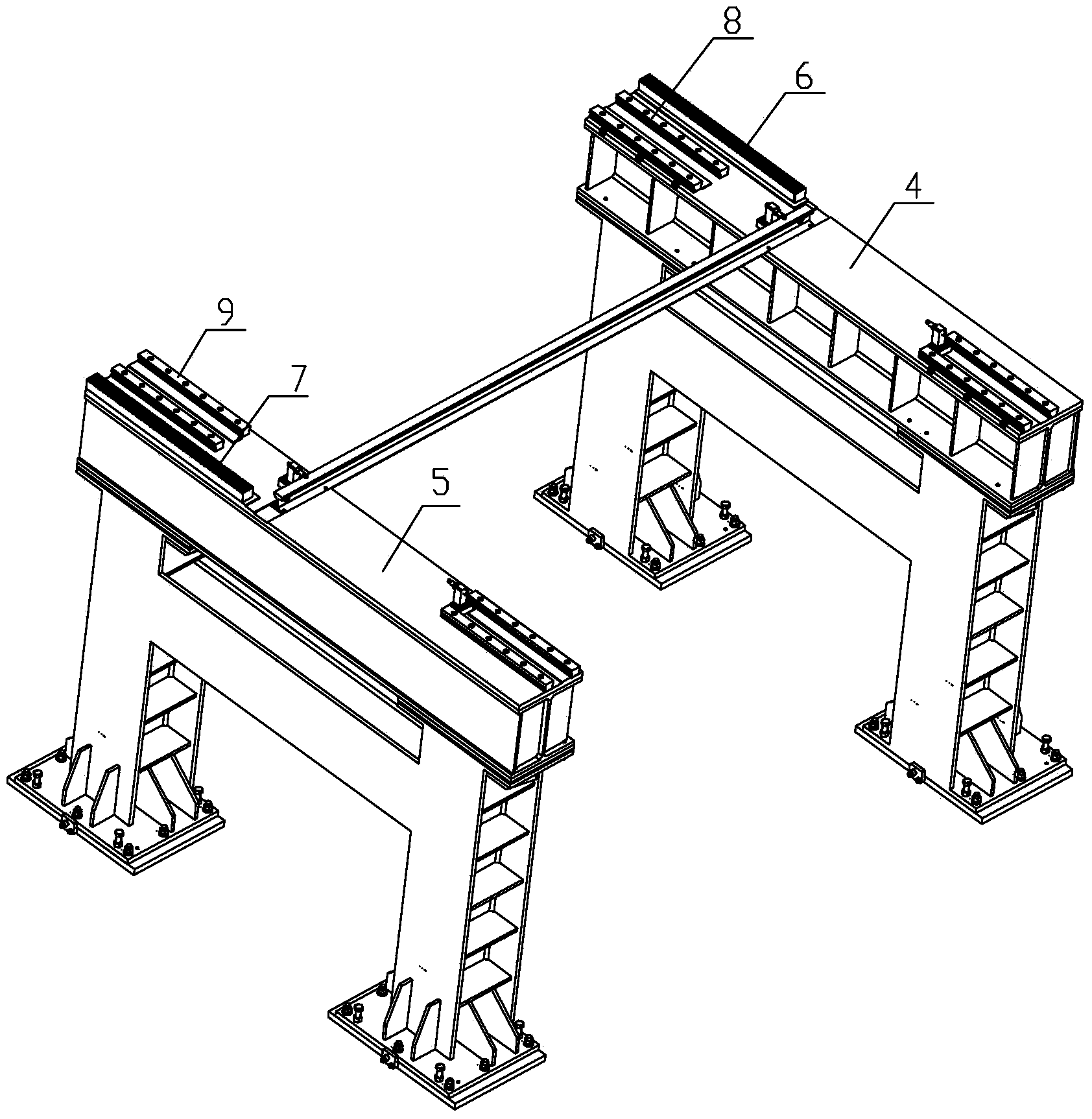
[0033] The structure of the bottom bracket part is as figure 2 As shown, it mainly includes two parts: the left side bracket 5 and the right side bracket 4. The left side bracket 5 is equipped with a left rack 7; the right side bracket 4 is equipped with a right rack 6 and a left rack 7 is used. To mesh with the left transmission gear 22 in the left driven transmission box 20, the right rack 7 is used to mesh with the right transmission gear 32 in the right driving transmission box 21; through the left transmission gear ...


PUM


Abstract

The invention relates to an automatic feeding device. The automatic feeding device comprises a bottom support part, an upper transmission part and a conveying suspender. The bottom support part comprises a left support and a right support, a left rack is installed on the left support, and a right rack is installed on the right support. Left guide strips are installed at the front end of the left support and the rear end of the left support and right guide strips are installed at the front end of the right support and the rear end of the right support. The upper transmission part comprises a left transmission assembly and a right transmission assembly. Left sliding blocks on the left transmission assembly are matched with the left guide strips, right sliding blocks on the right transmission assembly are matched with the right guide strips, left conveying boat bodies on the left transmission assembly and right conveying boat bodies on the right transmission assembly are equal in number and corresponding in position in a left-and-right mode, and the left end of the conveying suspender and the right end of the conveying suspender are supported by the left conveying boat bodies and the right conveying boat bodies respectively. The automatic feeding device is ingenious in structure, reasonable in design and capable of realizing automatic feeding between a phosphorization line and a powder spraying line, improves the production efficiency and lowers the labor intensity.

Description

technical field [0001] The invention relates to a feeding device, in particular to an automatic feeding device installed between a parts phosphating line and a powder spraying line, and belongs to the technical field of mechanical parts processing and manufacturing. Background technique [0002] Before powder spraying (painting) on ​​the surface of mechanical parts, the parts need to undergo pretreatment processes such as phosphating, pickling, drying, etc. After the pretreatment of the workpiece, the parts need to be hung on the powder spraying line (painting), and then spray The powder line is automatically sprayed to complete the automatic powder spraying (painting) process of the parts. In the existing production enterprises, the transition of parts from the phosphating line to the powder spraying line is completely done manually. The degree of automation is low, the labor intensity is high, and the production efficiency is low, which cannot meet the needs of automation ...

Claims


Application Information

Patent Timeline
Patent Type & Authority Applications(China)
IPC IPC(8): B65G17/20B65G17/32
Inventor 朱金权
Owner WUXI BEST PRECISION MACHINERY
Why Eureka
Try Eureka