Constant-tension pay-off rack
A pay-off frame and constant tension technology, applied in the field of pay-off racks, can solve the problems of inapplicability, power loss, and complex structure of conductive cables, and achieve the effects of timely adjustment, simple control, and small number of adjustments
- Summary
- Abstract
- Description
- Claims
- Application Information
AI Technical Summary
Problems solved by technology
Method used
Image

Examples
Embodiment 1
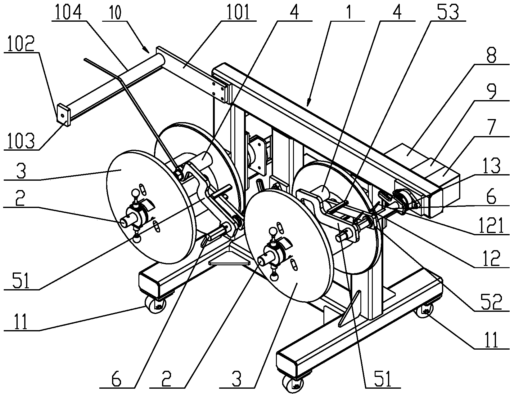
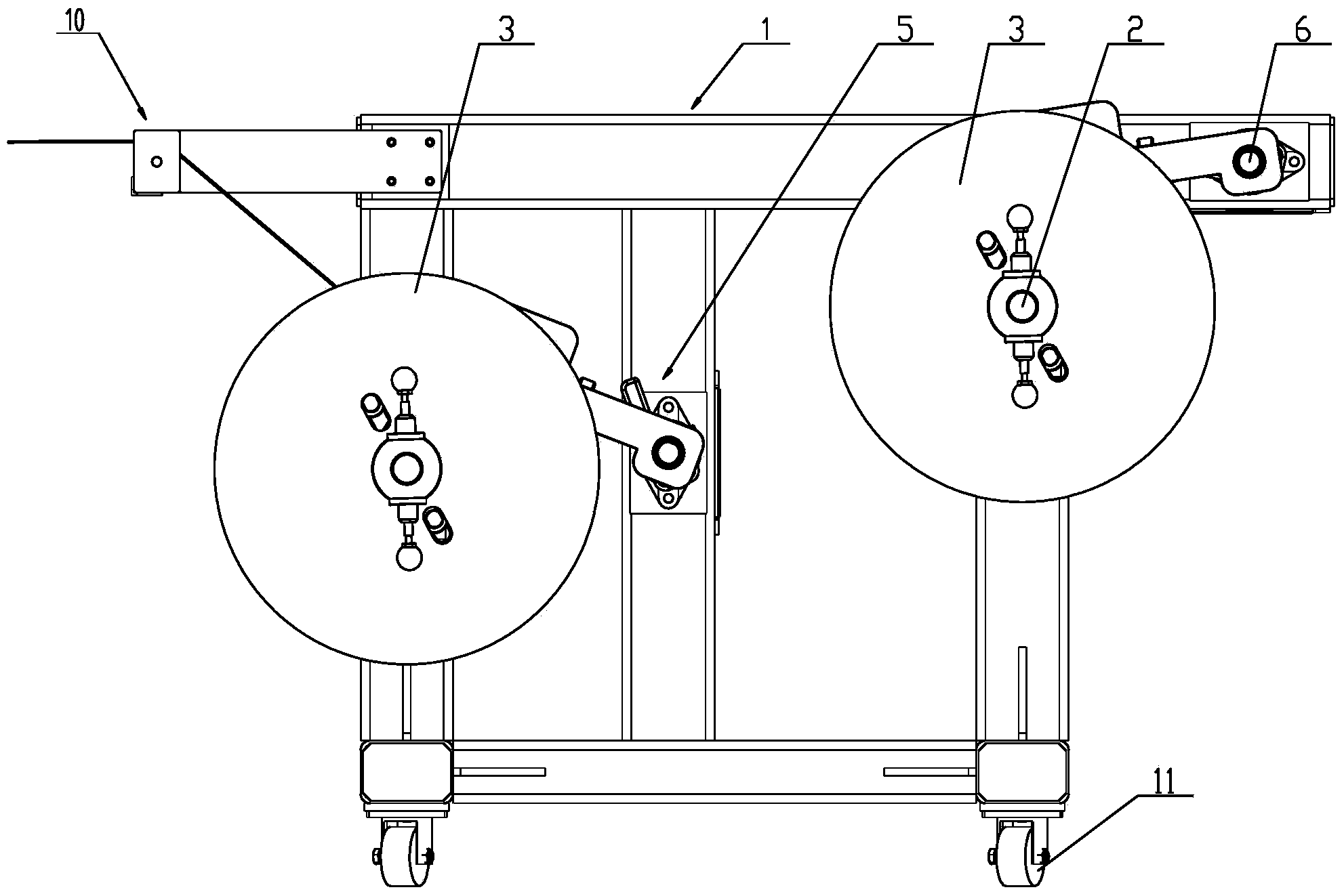
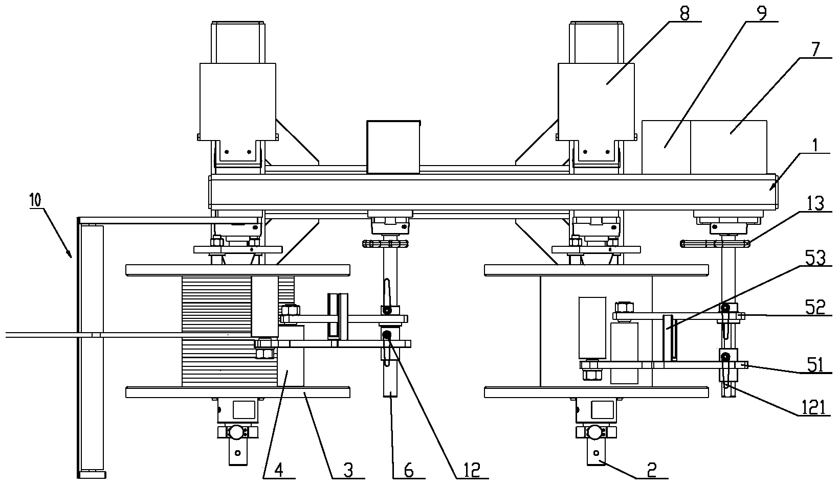
[0037] like Figure 1 to Figure 3 As shown, a constant tension pay-off frame of the present invention includes a bobbin 2 arranged on a frame 1, a bobbin 3 is installed on one side of the bobbin 2, and when the bobbin 2 rotates, the bobbin 3 is The bobbin 2 drives synchronous rotation. The other side of bobbin 2 is installed brake 8.
[0038] A pressure roller shaft 6 is also arranged on the frame 1, a pressure roller arm group 5 and a pressure roller handle 13 are installed on one side of the pressure roller shaft 6, and an angle sensor 7 is installed on the other side. The pressure roller shaft 6 is a round shaft, one end of the first pressure roller arm 51 and the second pressure roller arm 52 is sleeved on the pressure roller shaft 6, and the connection between the first pressure roller arm 51 and the second pressure roller arm 52 and the pressure roller shaft is set There is a screw hole matching with the top wire 12, and a positioning groove for matching the top wire i...
Embodiment 2
[0046] The difference between this preferred embodiment and the first preferred embodiment is that this preferred embodiment also includes an alignment roller set 10 .
[0047] like Figure 1 to Figure 3As shown, the group of alignment rollers 10 includes a roller support plate 101 , a roller angle iron 102 , a roller support plate 103 and a roller shaft 104 . The roller set 10 is located on the side of the bobbin 3 away from the pressure roller shaft and not lower than the upper top surface of the bobbin when the winding is at its maximum winding. The roller support plate 101 is a rectangular iron plate, which is fixedly connected with the upper corner of the frame 1 . The roller shaft angle iron 102 is fixedly connected to the roller shaft support plate 101 at 90 degrees, and is parallel to the ground. One end of the roller angle iron 102 is connected to the roller support plate 101 , and the other end is fixedly connected to the roller support plate 103 . A roller shaft ...
Embodiment 3
[0050] The difference between this preferred embodiment and preferred embodiment 1 or preferred embodiment 2 is that the frame 1 can be welded by square steel, channel steel, angle iron or their combination, and can also be other detachable installations. The positions of the bobbin 2 and the roller shaft 6 on the frame 1 are not limited, and the quantity is not limited. The installation position of the angle sensor 7 is not limited, as long as it can receive the angle change signal when the pressure roller arm group 5 rotates. The installation position of the controller 9 is not limited, as long as it can receive the signal output by the angle sensor 7 and can transmit the output signal of the controller 9 to the brake 8 . The installation position of the brake 8 is not limited, as long as it can receive the output signal of the controller 9 and control the torque of the winding shaft 2 . The installation position of the pressure roller handle 13 is not limited, as long as i...
PUM
 Abstract
Description
Claims
Application Information
 - R&D
- Intellectual Property
- Life Sciences
- Materials
- Tech Scout
- Unparalleled Data Quality
- Higher Quality Content
- 60% Fewer Hallucinations
Browse by: Latest US Patents, China's latest patents, Technical Efficacy Thesaurus, Application Domain, Technology Topic, Popular Technical Reports.
© 2025 PatSnap. All rights reserved.Legal|Privacy policy|Modern Slavery Act Transparency Statement|Sitemap|About US| Contact US: help@patsnap.com