Self-rotating needle

A self-rotating and needle-punching technology, which is applied in acupuncture machines, textiles, papermaking, non-woven fabrics, etc., can solve the problems of increased investment by non-woven fabric manufacturers, low fiber bundle work efficiency, and increased needle consumption. Small impact force, improved entanglement force, and improved physical properties

Active Publication Date: 2015-11-11
青岛锦钻针业有限公司
View PDF5 Cites 1 Cited by
  • Summary
  • Abstract
  • Description
  • Claims
  • Application Information

AI Technical Summary

Problems solved by technology

[0002] At present, the working section and the needle bar of the lancets produced at home and abroad are all made in one piece. The working section and the needle bar are fixed and cannot be rotated relative to each other. The hooked fibers penetrate into the thick material and form loose fiber bundles perpendicular to the fiber web in the fiber web. The work efficiency is low and the entanglement is not firm. It can only be compensated by increasing the number of needling machines and increasing the number of needles, resulting in The investment of non-woven fabric manufacturers has increased, the consumption of needles has increased, and a large amount of manual work is required to continuously replace needles.
At present, for thick and heavy needle-punched non-woven products, poor entanglement and delamination due to low peeling force are problems in the world, which need to be solved urgently

Method used


Image

  • Self-rotating needle
  • Self-rotating needle
  • Self-rotating needle

Examples


Embodiment 1

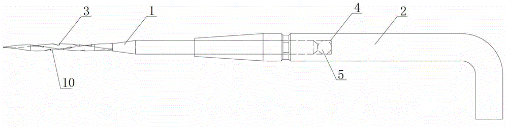
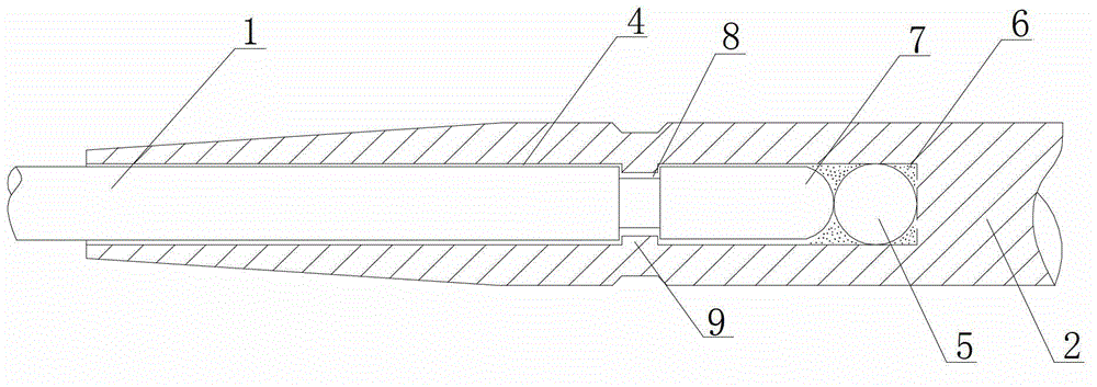
[0024] Such as figure 1 , figure 2 As shown, the self-rotating needle of the present invention includes a needle body 1 and a needle shaft 2, barbed hooks 3 are arranged at intervals on the needle body 1, the needle body 1 and the needle shaft 2 are separately arranged, and one side of the needle shaft 2 is provided with a blind hole 4 , the needle body 1 is inserted into the blind hole 4 and rotates relative to the blind hole.

[0025] The needle body 1 is provided with a lock ring 8 sunken inwardly, and the needle bar 2 is provided with an inwardly protruding card table 9 corresponding to the lock ring, and the card table 9 is stuck on the periphery of the lock ring 8 and maintains a certain gap. The ring 8 is free to rotate relative to the deck 9 . A protrusion 7 is provided at the end of the needle body, and a steel ball 5 is provided at the bottom of the blind hole, and the steel ball 5 contacts with the protrusion 7 at one point. The protrusion 7 adopts a sphere. Gr...

Embodiment 2

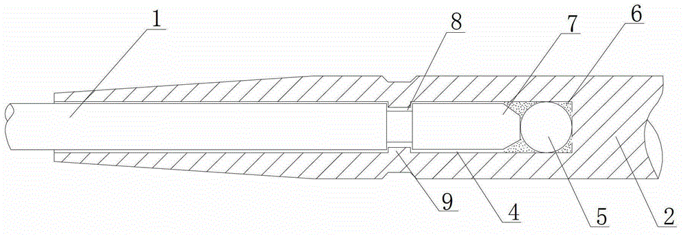
[0028] Such as image 3 As shown, the protrusion 7 adopts a trapezoidal cylinder.

[0029] Others are with embodiment 1.

Embodiment 3

[0031] Such as Figure 4 As shown, the side of the needle bar 2 connected with the needle body 1 is provided with four opening grooves 11 along the axial direction, and the opening of the blind hole 4 is provided with four inverted bosses 12 along the inner circumference of the needle bar 2, and the needle body 1 A locking groove 13 is provided at the position corresponding to the inverted boss 12 , and the inverted boss 12 is stuck in the locking groove 13 .

[0032] When in use, the needle body 1 is inserted into the needle bar 2, since the inner side of the needle bar 2 is provided with an inverted boss 12, and the needle body 1 is provided with a card slot 13, after the needle body 1 is inserted into the needle bar 2, the inverted boss 12 is just stuck in the In the slot 13, the needle body 1 and the needle bar 2 can be positioned due to the inversion of the boss, and the needle body 1 can rotate freely relative to the needle bar 2. When the needle body 1 is damaged, the ...


PUM


Abstract

The invention relates to non-woven product manufacturing equipment, in particular to a component of a needle machine, and discloses an automatic-rotating felting needle. The automatic-rotating felting needle comprises a needle body (1) and a needle rod (2). Hooks (3) are arranged on the needle body (1) at intervals. The needle body (1) and the needle rod (2) are arranged separately. A blind hole (4) is formed at one end of a non-bent handle of the needle rod (2), and the needle body (1) is inserted into the blind hole (4) to rotate relative to the blind hole. The felting needle rotates when penetrating fiber nets, so that twining force and cohesive force among fibers are greatly increased, the fibers are twined firmly and are not easy to layer due to high releasing force, length of a production line is shortened, production efficiency is improved, and service life of the felting needle is prolonged.

Description

technical field [0001] The present invention relates to a device for producing nonwoven products, in particular to a part of a needling machine. Background technique [0002] At present, the working section and the needle bar of the lancets produced at home and abroad are all made in one piece. The working section and the needle bar are fixed and cannot be rotated relative to each other. The hooked fibers penetrate into the thick material and form loose fiber bundles perpendicular to the fiber web in the fiber web. The work efficiency is low and the entanglement is not firm. It can only be compensated by increasing the number of needling machines and increasing the number of needles, resulting in The increased investment of non-woven fabric manufacturers has increased the consumption of needles, and it also requires a lot of manual labor to continuously replace needles. At present, for thick and heavy needle-punched non-woven products, poor entanglement and delamination due...

Claims


Application Information

Patent Timeline
Patent Type & Authority Patents(China)
IPC IPC(8): D04H18/02
Inventor 薛同乐薛淞
Owner 青岛锦钻针业有限公司
Why Eureka
Try Eureka