High-power ultra-short laser real-time near field intensity distribution measuring device

A technology of intensity distribution and measuring device, which is applied in the direction of photometry and instruments using electric radiation detectors, can solve the problems of not being able to obtain the intensity distribution of laser near-field at the same time, and achieve the effect of simple structure, low cost and convenient adjustment

Inactive Publication Date: 2014-04-09
LASER FUSION RES CENT CHINA ACAD OF ENG PHYSICS
View PDF3 Cites 17 Cited by
  • Summary
  • Abstract
  • Description
  • Claims
  • Application Information

AI Technical Summary

Problems solved by technology

[0003] In order to overcome the shortcomings that the existing measurement technology cannot simultaneously obtain the laser near-field intensity distribution at any moment and the pulse time waveform in any space, the present invention provides a high-power ultra-short laser real-time near-field intensity distribution measurement device

Method used


Image

  • High-power ultra-short laser real-time near field intensity distribution measuring device
  • High-power ultra-short laser real-time near field intensity distribution measuring device
  • High-power ultra-short laser real-time near field intensity distribution measuring device

Examples


Embodiment 1

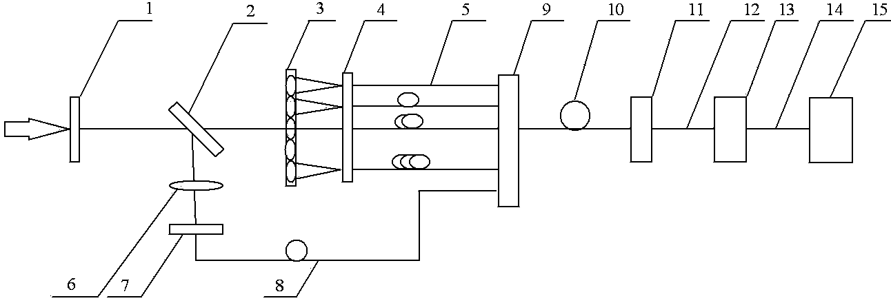
[0016] figure 1 It is a schematic diagram of the optical path structure of the high-power ultrashort laser real-time near-field intensity distribution measuring device of the present invention. exist figure 1 Among them, the high-power ultra-short laser real-time near-field intensity distribution measurement device of the present invention, in the measurement device, an attenuator 1 and a beam splitter 2 are arranged in sequence on the incident direction of the high-power laser pulse; the laser pulse passes through the The beam splitter 2 is divided into transmitted light and reflected light, and a micro-convex lens array 3, an optical fiber splitter 4, and a delay fiber group 5 are sequentially arranged on the transmitted light path of the beam splitter 2, and are sequentially arranged on the reflected light path of the beam splitter 2 Convex lens 6, fiber holder 7, and reference fiber 8; the transmitted light passes through the micro-convex lens array 3 and the fiber splitt...

Embodiment 2

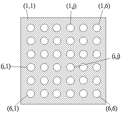
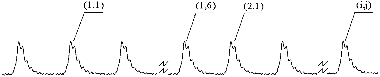
[0037] This embodiment has the same optical path structure and data processing process as Embodiment 1, except that the micro-convex lenses in the micro-convex lens array are arranged in concentric circles. The i in the number (i, j) represents the serial number of the ring counted from the inside to the outside, and j represents the number of the lenticular lens on the i-th ring.


PUM


Abstract

The invention provides a high-power ultra-short laser real-time near field intensity distribution measuring device. An attenuating piece and a beam splitter are sequentially placed in the device in the incidence direction of high-power laser pulses. A micro-lens array, an optical fiber distributor, a delay optical fiber set, an optical fiber beam combiner, transmission optical fibers, a quick phototube and a high-speed oscilloscope are sequentially placed in the transmission direction of the beam splitter. An optical fiber clamping device and reference optical fibers are sequentially placed in the reflecting direction of the beam splitter. The delay optical fiber set and the reference optical fibers are connected to the optical fiber beam combiner to form single output, then the single output is projected to the quick phototube through the transmission optical fibers, electric pulse sequences are formed on the high-speed oscilloscope, and at last, a computer is used for conducting data processing. According to the high-power ultra-short laser real-time near field intensity distribution measuring device, the micro-lens array is used for conducting spatial splitting sampling and optical fiber beam combining time division multiplexing transmission, and various kinds of information such as incident laser beam real-time near field intensity distribution information and pulse time waveform information are obtained through the waveform splicing reconstruction technology. The high-power ultra-short laser real-time near field intensity distribution measuring device is low in cost, simple in structure and convenient to adjust.

Description

technical field [0001] The invention belongs to the technical field of high-power laser testing, and in particular relates to a high-power ultra-short laser real-time near-field intensity distribution measuring device. Background technique [0002] The near-field intensity distribution and pulse time waveform of the laser beam are important indicators for evaluating laser performance. In the strong-field physics experiment under the action of ultrashort laser, it is necessary to know the near-field intensity distribution of the laser at any time and the pulse in any space in real time. waveform. At present, time-resolved near-field measurements mainly use framing cameras or streak cameras. Framing cameras can obtain the laser near-field intensity distribution at discrete moments, but pulse time waveform information cannot be obtained; while streak cameras can obtain pulses in one-dimensional space. Time waveform information cannot obtain two-dimensional spatial intensity di...

Claims


Application Information

Patent Timeline
Patent Type & Authority Applications(China)
IPC IPC(8): G01J1/42G01J11/00
Inventor 夏彦文孙志红张崑唐军卢宗贵元浩宇吕嘉坤
Owner LASER FUSION RES CENT CHINA ACAD OF ENG PHYSICS
Why Eureka
Try Eureka