Brushless direct current motor rotor position detecting device and phase changing method

A technology of rotor position detection and brushed DC motor, which is applied in the direction of electronic commutator, etc., can solve the problems of difficult implementation and complicated hardware circuit, and achieve the effects of simplified acquisition, smooth operation and speed regulation, and accurate commutation operation

Inactive Publication Date: 2014-04-09
NANJING UNIV OF SCI & TECH
View PDF3 Cites 11 Cited by
  • Summary
  • Abstract
  • Description
  • Claims
  • Application Information

AI Technical Summary

Problems solved by technology

Integrate the waveform signal, the hardware circuit is complicated, and it is difficult to realize

Method used


Image

  • Brushless direct current motor rotor position detecting device and phase changing method
  • Brushless direct current motor rotor position detecting device and phase changing method
  • Brushless direct current motor rotor position detecting device and phase changing method

Examples


Embodiment

[0030] The motor used in the implementation example is a compressor motor used in a DC inverter air conditioner, and its parameters are as follows:

[0031] (1) Motor type: brushless DC motor (BLDCM);

[0032] (2) Number of pole pairs: p=2;

[0033] (3) Rated speed: n=3600rpm;

[0034] (4) Rated output power: W = 650W;

[0035] (5) Winding resistance of each phase: r=0.9Ω (20°C);

[0036] (6) Winding inductance per phase: L σ = 3.35mH;

[0037] (7) Working frequency: f=20~190Hz;

[0038] (8) Moment of inertia of rotor: J=6.55×10 -4 (Kg m 2 );

[0039] (9) Potential coefficient Ke=13.2 (mV / rpm);

[0040] (10) Torque coefficient K T = 0.392 (N·m / A).

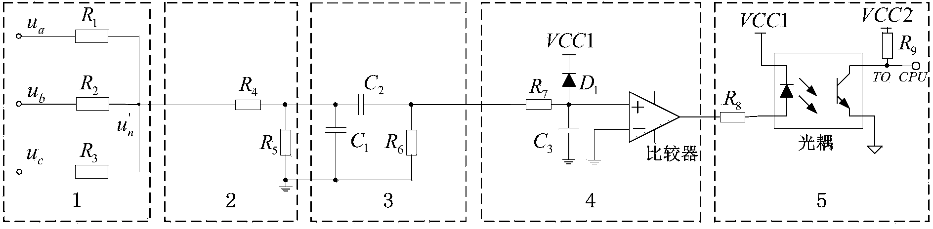
[0041] The Y-type network input terminal of the brushless DC motor position detection device is connected to the three-phase terminal voltage of the motor, and the obtained simulated neutral point voltage is divided by a resistor through a voltage dividing circuit, and the third harmonic of the counter electromotive forc...


PUM


Abstract

The invention discloses a brushless direct current motor rotor position detecting device based on the counter EMF triple frequency harmonic and a phase changing method suitable for the brushless direct current motor rotor position detecting device. The brushless direct current motor rotor position detecting device is composed of a Y-shaped connecting three-phase symmetrical resistance network, a voltage bleeder circuit, a band-pass filtering circuit, a zero passage comparison circuit and an optoelectronic isolation circuit. According to the detecting device, the simulation neutral points are built through the star-shaped three-phase symmetrical resistance network, the counter EMF triple frequency harmonic component is extracted from the simulation neutral points, zero passage signals of the counter EMF triple frequency harmonic component are obtained by comparing the counter EMF triple frequency harmonic component with the grounding end, and a microprocessor calculates the zero passage time of the three-phase counter EMF of a brushless direct current motor according to the two times of zero passage signals of the detecting device and the last action time of a switch tube and controls the phase changing according to the zero passage time. By means of the detecting method, the number of components of the rotor position detecting device can be reduced, and the reliability of detecting can be improved.

Description

technical field [0001] The invention belongs to the field of motors, in particular to a brushless direct current motor (BLDC) rotor position detection device and a phase commutation method. Background technique [0002] The back EMF of the brushless DC motor is a trapezoidal wave, and the power supply current is a square wave. The control system does not have high requirements for the rotor position signal, and only needs to obtain several discrete key position signals of the rotor. Brushless DC motors not only have the advantages of simple structure, reliable operation, and convenient maintenance of AC motors, but also have the characteristics of high operating efficiency and good speed regulation performance of DC motors, coupled with low cost, they are more and more widely used. [0003] There are two main control methods for brushless DC motors: position sensor control and position sensorless technology control. The position sensor control method and control circuit are...

Claims


Application Information

Patent Timeline
Patent Type & Authority Applications(China)
IPC IPC(8): H02P6/16
Inventor 李强王瑞霞蔡小玲杨伟徐斌冯承超
Owner NANJING UNIV OF SCI & TECH
Why Eureka
Try Eureka