
Focusing device and laser cutting device with the same

A focusing device and laser cutting technology, which is applied in laser welding equipment, manufacturing tools, welding equipment, etc., can solve the problems of unfavorable laser cutting promotion and increased equipment use costs, and achieve a wide cutting range, simplify the preparation process, and reduce costs. Effect

Active Publication Date: 2016-06-22
江苏亚威创科源激光装备有限公司
View PDF8 Cites 0 Cited by
  • Summary
  • Abstract
  • Description
  • Claims
  • Application Information

AI Technical Summary

Problems solved by technology

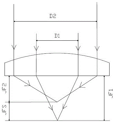
However, it is very difficult to manufacture such a focusing lens with two focal points
Secondly, in the process of use, lenses with different focal lengths need to be replaced from time to time according to the thickness of the workpiece, which increases the cost of equipment use and is not conducive to the promotion of laser cutting

Method used


Image

  • Focusing device and laser cutting device with the same
  • Focusing device and laser cutting device with the same
  • Focusing device and laser cutting device with the same

Examples


Embodiment 1

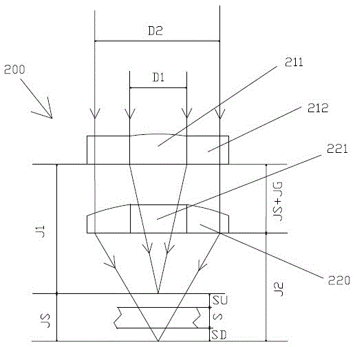
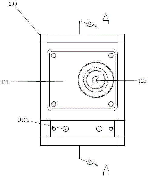
[0035] see Figure 2 to Figure 12 , the focus device (not labeled) used in the laser cutting device of the present invention is provided with a lens 200, an adjustment mechanism 300 for adjusting the position of the lens 200, and a housing 100 for accommodating the adjustment mechanism 300. The housing 100 is provided with a front wall 110 and a The front wall 110 is opposite to the rear wall 120, and the front wall 110 is provided with an openable protective cover 111, which is convenient for adjustment operation. The focusing device also includes an aperture drawer 400 in which the two focal points of the auxiliary adjustment lens 200 are located on the same optical axis.

[0036] The lens 200 includes a central focusing film 210 and a ring focusing lens 220 . The central focusing sheet 210 is provided with a central focusing lens 211 and an annular plane mirror 212 surrounding the central focusing lens 211 and used for fixing the central focusing lens 211 . The outer diam...

Embodiment 2

[0049] see Figure 13 It is the optical path diagram of the bifocal lens of another preferred embodiment of the present invention, which differs from Embodiment 1 only in that the first focus is located above the upper surface of the workpiece, and the second focus is located below the lower surface of the workpiece. Generally, the diameter of the laser cutting nozzle 500 is relatively small. In the above-mentioned embodiment, the diameter of the laser beam focused by the lens 200 is relatively large, and part of the light may be blocked by the laser cutting nozzle 500, or the laser cutting nozzle 500 needs to be The diameter should be designed larger. In this embodiment, the diameter of the laser beam focused by the lens 200 is relatively small, and all light rays can be emitted from the laser cutting nozzle 500 .

[0050] The beneficial effects of the present invention are: compared with the prior art, the focusing device of the present invention forms two focal points thro...


PUM


Abstract

A focusing device used in a laser cutting device is provided with a lens and an adjusting mechanism which adjusts the position of the lens. The lens comprises a center focusing piece and an annular focusing lens. The center focusing piece is provided with a center focusing lens and an annular plane mirror which surrounds the center focusing lens and is used for fixing the center focusing lens. The outer diameter and the ring width of the annular focusing lens are the same as those of the annular plane mirror. The adjusting mechanism comprises a centering device and a distance adjusting device. The centering device is used for adjusting the focuses of the center focusing lens and the annular focusing lens, so that the focuses are placed on the same optical axis. The distance adjusting device adjusts the distance between the focuses of the center focusing lens and the annular focusing lens. According to the focusing device, the manufacturing technology of focusing lens with different curvature radiuses is simplified, adjusting of the distance between the two focuses is convenient, the cutting range is wide, and cost is low.

Description

technical field [0001] The invention relates to a focusing device, in particular to a focusing device with double focal points and adjustable distance between the two focal points and a laser cutting device with the focusing device. Background technique [0002] Laser cutting is the use of high-power-density laser beams to scan the surface of the workpiece, heat the material to thousands to tens of thousands of degrees Celsius in a very short period of time to melt or gasify the material, and then use high-pressure gas to melt or vaporize the material from the cutting seam Blow away to achieve the purpose of cutting materials. Since the traditional mechanical knife is replaced by an invisible beam, the mechanical part of the laser cutter head has no contact with the workpiece, and will not scratch the surface of the workpiece during work. In addition, laser cutting also has the advantages of high precision, fast cutting speed, smooth cutting, material saving, and low proces...

Claims


Application Information

Patent Timeline
Patent Type & Authority Patents(China)
IPC IPC(8): B23K26/035B23K26/38
CPCB23K26/02B23K26/38
Inventor 朱正强吴德林
Owner 江苏亚威创科源激光装备有限公司
Learn More