Method for lowering large cofferdam

A cofferdam decentralization and construction method technology, applied in the direction of infrastructure engineering, construction, etc., can solve the problems of cofferdam structure damage, time-consuming and labor-intensive installation, and damage to the lifting system, so as to achieve smooth and safe decentralized construction, save construction materials, The effect of reducing construction costs

Active Publication Date: 2014-04-16
CHINA RAILWAY MAJOR BRIDGE ENG GRP CO LTD +1
View PDF5 Cites 6 Cited by
  • Summary
  • Abstract
  • Description
  • Claims
  • Application Information

AI Technical Summary

Problems solved by technology

[0006] When using the heavy-duty lifting and lowering device 1 to lift the cofferdam 2, due to the uneven distribution of water in the open bottom compartment 4, it is easy to cause the cofferdam 22 to be in an unbalanced load state, and the force on the cofferdam 2 is uneven, and the cofferdam 2 is relatively heavy. easily damaged
[0007] (2) The large-scale heavy-duty lifting and lowering device 1 has large synchronous control deviation, which can easily cause accidents due to uneven force on the inner bracket, and the cofferdam has a large area and heavy weight. The large-scale heavy-duty lifting and lowering device 1. It is very difficult to realize synchronous control, and it is very easy to cause damage to the lifting system, and in severe cases, it will cause damage to the cofferdam structure
[0008] (3) It is necessary to install a heavy-duty lifting and lowering device 1 with a large load on the top of the steel casing 3. This large-scale heavy-duty lifting and lowering device 1 not only requires a large amount of construction materials, but also requires complicated processing, and the installation is time-consuming and laborious.

Method used


Image

  • Method for lowering large cofferdam
  • Method for lowering large cofferdam
  • Method for lowering large cofferdam

Examples


Embodiment Construction

[0029] The present invention will be described in further detail below in conjunction with the accompanying drawings and embodiments.

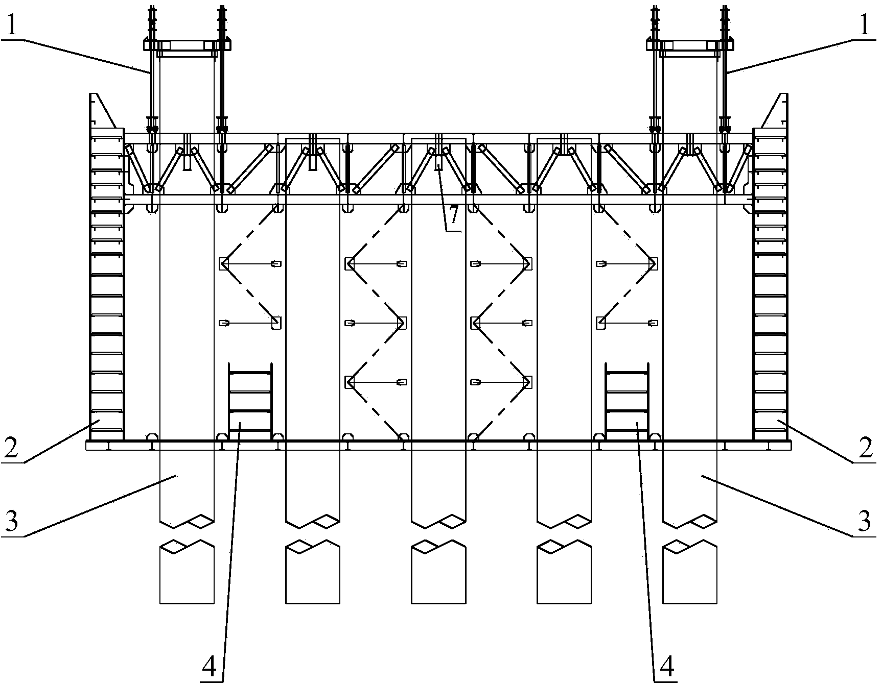
[0030] see image 3 As shown, a kind of large-scale cofferdam construction method in the embodiment of the present invention, comprises the following steps:

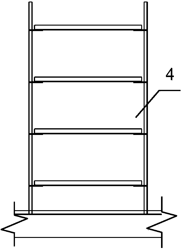
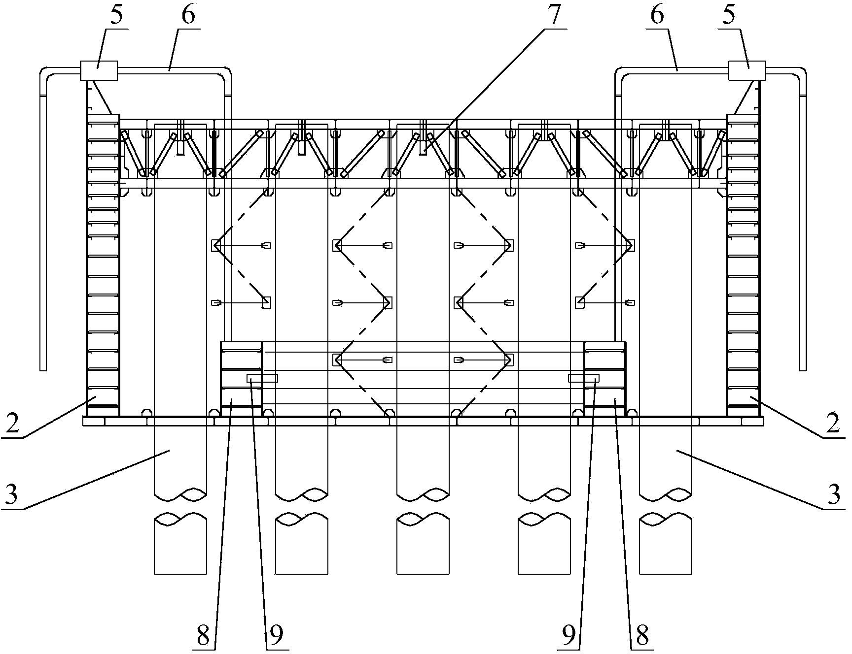
[0031] S1: see figure 2 As shown, the cofferdam 2 includes an open bottom compartment 4, and the open bottom compartment 4 includes several transverse bottom compartments and some longitudinal bottom compartments; see image 3 As shown, several transverse bottom compartments and several longitudinal bottom compartments in the cofferdam 2 are connected through internal communication pipes 9, and the internal communication pipes 9 are located at the junction of each transverse bottom compartment and longitudinal bottom compartment; see image 3 and Figure 4 As shown, a bottom compartment cover 10 is installed on the top of the open bottom compartment 4 to form a connected closed botto...


PUM


Abstract

The invention discloses a method for lowering a large cofferdam, and relates to the technical field of bridge foundation construction. The method comprises the following steps that a transverse bottom bay and a longitudinal bottom bay in the cofferdam are communicated through an inner communication pipe, bottom bay covers are arranged at the tops of the bottom bays, and a communicated sealed bottom bay system is formed; guide pipe systems with water drawing devices are welded to the top of the sealed bottom bay system, and each guide pipe system comprises one end communicated with the sealed bottom bay system and the other end stretching into water in the lowering process; the cofferdam is transported in a floating mode and fixed, water in the sealed bottom bay system is drawn out, and when the cofferdam floats upwards to be separated from a hanging pile telescopic beam, the hanging pile telescopic beam is dismounted; water is poured into the sealed bottom bay system, the cofferdam is lowered in place, the hanging pile telescopic beam is fixed, and the water drawing device is dismounted; concrete is poured into the sealed bottom bay system through the guide pipe systems; bottom sealing construction is carried out; the guide pipe systems are dismounted. According to the method, the cofferdam can rise or sink freely at different water levels fast and stably, construction is safe, the construction period is shortened, and materials are saved.

Description

technical field [0001] The invention relates to the technical field of bridge foundation construction, in particular to a large-scale cofferdam construction method. Background technique [0002] see figure 1 and figure 2 As shown, the traditional cofferdam lowering system includes double walls of the cofferdam, a steel casing 3, an open bottom compartment 4, a telescopic beam for hanging piles 7, and a heavy-duty lifting and lowering device 1. The traditional cofferdam lowering construction method is as follows: After the cofferdam is floated in place, the elevation of the cofferdam is adjusted by adding water or pumping water into the double walls of the cofferdam, and the telescopic beam 7 for hanging piles is welded to the steel casing 3 to complete the steel casing 3 pile foundation construction. Then adopt the heavy-duty lifting and lowering device 1 to lift the cofferdam 2, remove the hanging pile telescopic beam 7 from the steel casing 3, and then use the heavy-du...

Claims


Application Information

Patent Timeline
Patent Type & Authority Applications(China)
IPC IPC(8): E02D19/04
Inventor 杨齐海张春新潘东发何加江徐进徐国亮刘润泽董继红赵成贵周伟
Owner CHINA RAILWAY MAJOR BRIDGE ENG GRP CO LTD
Why Eureka
Try Eureka